48
H I PE RG UA R D M V U PS
US ER M A N UA L
—
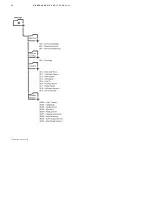
Figure 6.05: Energy
Storage enclosure
controller connections .
Please refer to project-specific documentation for details.
6.4.5 Demand Response Controller Application & Connections
It is possible to configure the HiPerGuard MV UPS to provide grid support services to aid the utility grid in the sup-
ply of power if ever the grid demand temporarily exceeds grid supply. This requires the connection to a third party
“Demand Response Controller” (DRC). The MV UPS communicates with the DRC via an Ethernet connection (Mod-
bus TCP). For a detailed description of Modbus registers, addresses and ranges, refer to the HiPerGuard MV UPS
Mod-bus TCP register map (2UCD400000E012). The MV UPS communicates to an external Demand Response Con-
troller via Modbus TCP. Figure 6.06 shows the connections.
A DRC, when enabled, uses the UPS PEBB's and battery as an additional source of power for occasions when grid
capacity is temporarily at or near its limit. It monitors grid conditions and influences the operation of the inverter
and battery management to give grid support as an when needed.
A portion of the battery’s capacity is allocated for grid support functions. If this capacity is not available, grid
support may be disabled to ensure that the battery has adequate capacity to perform UPS autonomy functions.
Note that DRC requests for support will be overridden at any time if the UPS considers that the request will com-
promise the UPS’s ability to protect the load.
—
Figure 6.06: Demand
Response Control-
ler connections.
Summary of Contents for HiPerGuard MV UPS
Page 58: ...58 HIPERGUARD MV UPS USER MANUAL Figure 7 04 Pages map ...
Page 84: ......


