background image

Installation and maintenance guide
1ZSC000563-AAB EN, REV. 6, 2019-09-12

31

Procedure

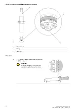
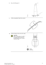
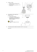
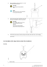
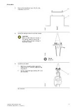
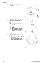
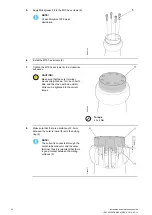
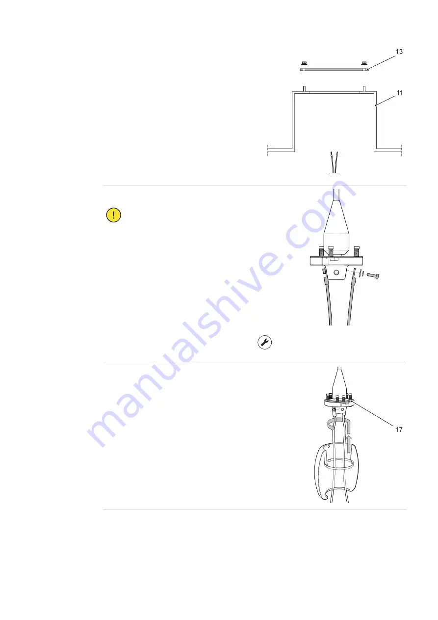
1.

Remove the transformer cover (13) from the
transformer turret (11).

G004927

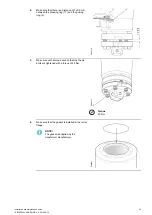
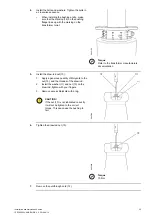
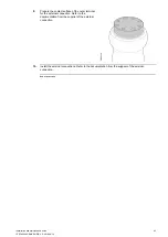
2.

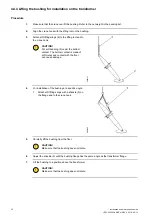
Install the winding cables to the bottom contact.

CAUTION!

Make sure that there is no tension in
the winding cables. Tension in the
winding cables will cause damage to
the bottom contact.

G004929

Torque

68 ±6 Nm

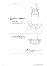
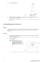
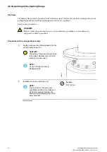
3.

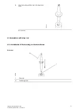
Install the end shield:

1.

Push the end shield carefully against the
pressing ring (17), until the springs are fully
compressed.

2.

Turn the end shield approximately 20°, to its
locked position.

G006202

End of instruction

Summary of Contents for GSBK 170

Page 1: ...1ZSC000563 AAB EN REV 6 2019 09 12 Transformer bushing type GSBK Installation and maintenance guide ...

Page 2: ...or any errors that may appear in this document ABB AB is not liable for any damage resulting from the incorrect interpretation of this document This document or parts thereof may not be reproduced or copied without ABB AB s consent It may not be distributed to others or used by unauthorized parties Any breaches to the above will be penalized with the support of applicable laws ...

Page 3: ...fixed bottom contact 22 4 4 Preparations with draw rod 27 4 4 1 Removal of the outer terminal 27 4 4 2 Removal of the lower draw rod with bottom contact from the bushing 28 4 4 3 Installation of the large bottom contact in the transformer 30 4 4 4 Lifting the bushing for installation on the transformer 32 4 5 Installation with draw rod 33 4 5 1 Installation of the bushing on the transformer 33 4 5...

Page 4: ...l of the bushing from the transformer fixed bottom contact 55 7 2 Removal of the bushing from the transformer draw rod 56 7 3 Re packing of the bushing 60 8 Spare parts 63 8 1 Summary 63 8 2 Spare parts 63 8 3 Special tools 64 9 Disposal and environmental information 67 9 1 Overview 67 9 2 Disposal and recycling 67 10 Reference 69 10 1 Summary 69 ...

Page 5: ...duct It is used for example to warn of such dangers as contact with high voltage explosion or fire risk risk for toxic gases risk of crushing impacts falls from high places etc CAUTION The round warning symbol warns that an accident could occur if the instructions are not observed and that this could result in personal injury and or damage to the product It is also used to warn of risks that entai...

Page 6: ...safety regulations Do not use ladders or platforms in poor weather conditions Working with heavy objects Do not walk under lifted objects Make sure that heavy objects are stable before starting work 1 3 Safety precautions Precaution Action Transformer oil Collect used transformer oil in drums Transformer oil is dangerous Fumes from hot oil can cause irritation to the respiratory organs and the eye...

Page 7: ...for immersed oil to SF6 service The bushing is of the dry gas free type with a resin impregnated paper RIP condenser core as the primary insulation Bushings of this design can be installed at any angle from vertical to horizontal General schematics G005122 1 Outer terminal 2 RIP condenser core 3 Mounting flange 4 RIP condenser core 5 End shield 6 Test voltage tap ...

Page 8: ...tenance guide 1ZSC000563 AAB EN REV 6 2019 09 12 Terminal system The bushing can be configured with one of two terminal systems the fixed bottom contact system or the draw rod system G005101 1 Draw rod 2 Fixed bottom contact ...

Page 9: ...outermost conductive layer to ground and must always be installed when the bushing is energized The maximum one minute test voltage for this test tap is 2 kVrms The test tap can be used as a power source if it is connected to an external capacitance The operating voltage is limited to 600 V CAUTION Do not energize the bushing without a test adapter or the cover installed The bushing is grounded th...

Page 10: ...perating voltage is limited to 6 kV CAUTION Do not energize the bushing without a test adapter or the cover installed The cover connects the outermost conductive layer to ground and will prevent damage to the bushing G000388 1 Stud 2 Cover 3 Grounding spring 4 O ring 2 2 Transformer testing To simplify the transformer testing several alternatives are available instead of using the GIS system The G...

Page 11: ... gas Maximum daily mean temperature 75 C Maximum pressure 850 kPa abs Minimum pressure 350 kPa abs Immersion medium Transformer oil Maximum daily mean oil temperature 90 C Maximum temporary oil temperature at normal load 100 C Maximum temporary oil temperature at short time overload 115 C Oil level in transformer Not lower than 30 mm from the bushing flange Maximum pressure of medium pg 100 kPa pg...

Page 12: ...C900362 ACB 1ZSC900362 ADB GSBK 420 1ZSC900420 AAA 1ZSC900420 ABA 1ZSC900420 AAB 1ZSC900420 ABB 1ZSC900420 ACA 1ZSC900420 ADA 1ZSC900420 ACB 1ZSC900420 ADB GSBK 550 1ZSC900550 AAA 1ZSC900550 ABA 1ZSC900550 AAB 1ZSC900550 ABB 1ZSC900550 ACA 1ZSC900550 ADA 1ZSC900550 ACB 1ZSC900550 ADB 2 3 2 Mechanical loading Maximum permitted static load on the outer terminal The load must be applied at the midpoi...

Page 13: ...EV 6 2019 09 12 13 Load on the outer terminal G006302 1 Cantilever load 2 Outer terminal Type Maximum cantilever load on the outer terminal Type test load 1 minute kN Maximum service load kN GSBK 170 4 2 GSBK 245 4 2 GSBK 362 4 2 GSBK 420 4 2 GSBK 550 4 2 ...

Page 14: ...Test load kNm In operation kNm Shearing load kN Compressive or tensile load kN GSBK 170 20 10 10 50 GSBK 245 40 20 14 70 GSBK 362 80 40 20 10 GSBK 420 80 40 20 10 GSBK 550 80 40 20 10 GIS pressure The limit SF6 gas pressures for the GIS side of the bushing Type Type test pressure 1 minute MPaabs Routine test pressure 1 minute MPaabs Maximum service pressure MPaabs GSBK 170 2 55 1 25 0 85 GSBK 245 ...

Page 15: ...he atmosphere replace it The bushing must be transported in the horizontal position Carefully inspect the bushing for damage after transportation 3 3 Storage Short term storage less than 6 months Make sure that the bushing is wrapped in the original or equivalent moisture proof wrapping If the drying agent inside the wrapping has been exposed to the atmosphere replace it The bushing can be stored ...

Page 16: ...t is in the transport box Keep the transport box protected from water when the bushing is stored outdoors Keep the bushing dry clean and protected against mechanical damage The bushing can be stored in both the vertical and horizontal positions The bushing is delivered from ABB in a transport box and the bushing is held in place by support blocks and fiberboard in the box G006274 3 4 Lifting 3 4 1...

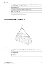
Page 17: ... soft lifting slings 2 3 Make sure that the angle of the soft lifting sling is not more than 20 4 Carefully lift the transport box 5 Set down the transport box on a flat surface End of instruction 3 4 2 Lifting the bushing out of the transport box Overview G005083 Procedure 1 Make sure that the crane is approved for lifting the weight of the bushing Refer to the weight on the rating plate 2 Open t...

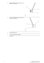
Page 18: ...09 12 3 Attach a soft lifting sling to the condenser core 1 and then to the crane hook G006857 4 Attach a soft lifting sling to the condenser core 1 and then to the crane hook G005085 5 Carefully lift the bushing 6 Lower the bushing onto soft bedding End of instruction ...

Page 19: ...connection of the soft lifting slings to the bushing flange Hydraulic jack 2769 897 A For removal and installation of the bottom contact Draw rod system Box spanner 9760 669 B For removal and installation of the bottom contact Draw rod system Tackle For installation of the bushing at a specific angle 4 2 Consumables Item Brand ABB part number Note Oil based Vaseline Fuchs 1171 5011 102 For treatme...

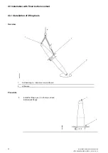
Page 20: ... REV 6 2019 09 12 4 3 Installation with fixed bottom contact 4 3 1 Installation of lifting tools Overview G005086 1 Soft bedding i e rubber mat or woodboard 2 Lifting eye Procedure 1 Install the lifting eyes 1 in the top end and intermediate flange G005089 ...

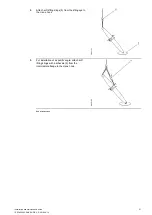
Page 21: ...REV 6 2019 09 12 21 2 Attach soft lifting slings 8 from the lifting eye to the crane hook G005137 3 For installation at a specific angle attach soft lifting slings with a schackle 9 from the intermediate flange to the crane hook G005105 End of instruction ...

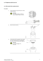
Page 22: ...12 4 3 2 Installation with fixed bottom contact G006208 1 Bottom contact 2 Bushing 3 Pulling ring Procedure 1 If the bushing has the optional transport container installed remove it CAUTION Do not cause damage to the RIP core when removing the transport container G005091 ...

Page 23: ... 7 0 5 mm between the pressing ring 17 and the pulling ring 3 G006215 3 Make sure with a torque wrench that the the six bolts are tightened with a torque of 40 Nm G006214 Torque 40 Nm 4 Make sure that the gasket is installed in the turret flange NOTE The gasket is supplied by the transformer manufacturer G006865 ...

Page 24: ... is installed in the correct orientation 2 Make permanent markings 16 on the bushing flange and the transformer turret G005107 7 Install the bolts and washers Tighten the bolts in a crosswise sequence When installing the bushing at site make sure that the marking 16 on the bushing flange lines up with the marking on the transformer turret G005108 Torque Refer to the transformer manufacturers docum...

Page 25: ...lifting eyes 1 G005089 9 Put the winding cables through the end shield G004325 10 Install the winding cables to the bottom contact CAUTION Make sure that there is no tension in the winding cables Tension in the winding cables will cause damage to the bottom contact G006212 Torque 68 6 Nm ...

Page 26: ...tion G006213 12 If the transformer will be oil filled with the atmospheric process 1 Remove the hex screws 6 2 Put the blades of two screwdrivers in the recesses 19 in the outer terminal 5 and carefully push them down to lift the outer terminal 5 straight up CAUTION Do not cause damage to the shield 18 G006307 13 The bushing is ready for oil filling of the transformer refer to Oil filling page 39 ...

Page 27: ... optional transport container installed remove it CAUTION Do not cause damage to the RIP core when removing the transport container G005091 2 Remove the hex screws 6 G005126 3 Put the blades of two screwdrivers in the recesses 19 in the outer terminal 5 and carefully push them down to lift the outer terminal 5 straight up CAUTION Do not cause damage to the shield 18 G006307 ...

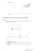
Page 28: ...ction 4 4 2 Removal of the lower draw rod with bottom contact from the bushing Overview The bottom contact is usually installed in the bushing when it is delivered from ABB the first step at the transformer factory is thus to remove it G005090 1 Upper draw rod 2 Lower draw rod with bottom contact 3 Bottom contact 4 Bushing ...

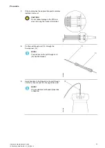
Page 29: ...not cause damage to the RIP core when removing the transport container G006350 2 Put the pull through cord 12 through the box spanner 13 NOTE The terminal on the pull through cord 12 has M8 threads G004924 3 Apply Vaseline to the threads on the pull through cord 12 then connect it to the upper draw rod NOTE Or use a lubricant with equal properties to Vaseline G005092 ...

Page 30: ...ll down the draw rod from the bottom end of the bushing and disassemble it at the lower joint 8 CAUTION Do not disassemble the joint 7 this increases the risk of incorrect assembly The joint 7 is locked with high strenght tread locking fluid grade 42 G005094 6 Carefully clean the bottom end of the bushing and the inside of the center hole Look for damage End of instruction 4 4 3 Installation of th...

Page 31: ...the bottom contact CAUTION Make sure that there is no tension in the winding cables Tension in the winding cables will cause damage to the bottom contact G004929 Torque 68 6 Nm 3 Install the end shield 1 Push the end shield carefully against the pressing ring 17 until the springs are fully compressed 2 Turn the end shield approximately 20 to its locked position G006202 End of instruction ...

Page 32: ...ON Put soft bedding 2 under the bottom contact The bottom contact is made of soft metal and contact with the floor can cause damage G005137 4 For installation of the bushing at a specific angle 1 Attach soft lifting slings with a shackle 9 on the flange and to the crane hook G005105 5 Carefully lift the bushing from the floor CAUTION Make sure that the bushing does not rotate 6 Adjust the shackle ...

Page 33: ... AAB EN REV 6 2019 09 12 33 8 Align the bushing with the hole in the transformer turret G004562 End of instruction 4 5 Installation with draw rod 4 5 1 Installation of the bushing on the transformer Overview G006866 1 Draw rod 12 Pull through cord ...

Page 34: ...AUTION Do not damage the stud bolts There is a risk of metal falling into the transformer NOTE Plastic sleeves put on two or three of the stud bolts will help to guide the flange and will prevent damage to the stud bolts G005100 3 When installing the bushing at the transformer factory 1 Make sure that the bushing is installed in the correct orientation 2 Make permanent markings 16 on the bushing f...

Page 35: ...Refer to the transformer manufacturers documentation 5 Install the draw rod nut 10 1 Apply a generous quantity of Molykote to the nut 10 and the threads of the draw rod 2 Install the washer 11 and nut 10 on the draw rod tighten with your fingers 3 Remove excess Molykote with a rag CAUTION If the nut 10 is not lubricated correctly it will not be tighten to the correct torque This can cause the bush...

Page 36: ...d nut washer and threads of the draw rod to be correctly lubricated The draw rod will not get the correct tension if the fasteners are not correctly lubricated this can cause the bushing to fail Procedure 1 Make sure that the draw rod nut and threads of the draw rod are correctly lubricaded and that the draw rod nut is tightened to 10 Nm 2 Measure the distance a NOTE The bushing is delivered with ...

Page 37: ...rench set to 140 Nm NOTE One turn of the nut corresponds to a 2 mm extension of the draw rod Type Extension CT 300 mm CT 300 mm GSBK 170 24 0 mm 24 5 mm GSBK 245 24 5 mm 25 0 mm GSBK 362 25 0 mm 25 5 mm GSBK 420 25 0 mm 25 5 mm GSBK 550 25 5 mm 26 0 mm G005111 4 Make sure with a torque wrench that the nut is tightened with a torque of more than 70 Nm and less than 140 Nm 5 Continue with Installati...

Page 38: ...aw rod nut Procedure 1 Install the hydraulic jack 8 2 Pull the draw rod with a force according to the table Type Force CT 300 mm CT 600 mm GSBK 170 39 5 kN 39 5 kN GSBK 245 39 1 kN 39 3 kN GSBK 362 39 1 kN 39 3 kN GSBK 420 39 0 kN 39 2 kN GSBK 550 39 4 kN 39 5 kN 3 Tighten the nut on the draw rod with your hand 4 Remove the hydraulic jack 8 End of instruction ...

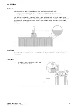
Page 39: ...as possible from the center tube of the bushing Because air is soluble in transformer oil air will go into the transformer oil and will cause its performance to deteriorate The amount of air that can be removed depends on the bushings position in relation to the transformers oil conservator G006346 Oil spillage Oil spillages that are not removed can be misstaken for oil leakage at a later time it ...

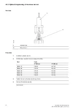
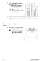
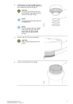
Page 40: ... the bushing NOTE Air is soluble in transformer oil thus as much as possible must be released from the bushing center tube G005102 3 Install the outer terminal refer to Installation of the outer terminal page 40 End of instruction 4 7 Installation of the outer terminal Procedure 1 Carefully clean the contact and gasket surfaces with a soft cloth and then apply Mobilgrease 28 CAUTION Do not use a w...

Page 41: ...m outer terminals A wire brush can make scratches in the silver coating NOTE Or use a lubricant with equal properties to Mobilgrease 28 NOTE When the outer terminal 5 is installed at site for grid operation replace the used O rings 3 with new O rings New O rings are supplied with the bushing G005098 3 Put the O rings 3 on the outer terminal 5 CAUTION Make sure that the guide ring 7 is in position ...

Page 42: ... CAUTION Make sure that the outer terminal moves straight down Turn each bolt a little and then the next bolt until all bolts can be tightened to the correct torque G005114 Torque 40 4 Nm 8 Make sure that there is a distance of 2 3 mm between the outer terminal 5 and the pulling ring 8 NOTE The current is conducted through the center tube conductor and the outer terminal thus it is important that ...

Page 43: ...are the contact surface of the outer terminal for the external connection Refer to the documentation from the supplier of the external connection G005128 10 Install the external connections Refer to the documentation from the supplier of the external connection End of instruction ...

Page 44: ...isfactory grounding can cause damage to equipment or death to personnel Procedure with a cone point set screw 1 Apply a large quantity of Mobilgrease 28 to the cone point set screw 13 CAUTION The quality of the cone point set screw is important stainless steel of A4 80 quality is recommended NOTE Or use a lubricant similar to Mobilgrease 28 G005115 2 Install the cone point set screw 13 NOTE The co...

Page 45: ... transformer G005116 3 Apply a large quantity of Mobilgrease 28 to the bolt 13 CAUTION The quality of the bolt is important stainless steel of A4 80 quality is recommended NOTE Or use a lubricant similar to Mobilgrease 28 4 Install the bolt 13 Torque M12 40 Nm 5 Connect the other end of the flexible cable 14 to the transformer NOTE This makes an electrical connection between the bushing and keepin...

Page 46: ...46 Installation and maintenance guide 1ZSC000563 AAB EN REV 6 2019 09 12 ...

Page 47: ...anuafacturers instructions Gas saturated transformer oil After the oil filling process has been completed wait for 24 hours before energizing the transformer De gassed transformer oil After the oil filling process has been completed wait for 6 hours before energizing the transformer A reduced oil level After the oil level has been restored wait 24 hours before energizing the transformer 5 2 Recomm...

Page 48: ...pacitance between the test voltage tap and the outer terminal C2 is the capacitance between the test voltage tap and ground NOTE The transport container must be removed before measuring the capacitance and dissipation factor tan δ Nominal capacitance The capacitance C2 depends on the transformer and it is not possible to give a nominal value that is valid for all service conditions Thus it is impo...

Page 49: ...th the correction factor given below Bushing core temperature C Correction factor to 20 C IEC 0 2 0 76 3 7 0 81 8 12 0 87 13 17 0 93 18 22 1 00 23 27 1 07 28 32 1 14 33 37 1 21 38 42 1 27 43 47 1 33 48 52 1 37 53 57 1 41 58 62 1 73 63 67 1 43 68 72 1 42 73 77 1 39 78 82 1 35 83 87 1 29 Procedure 1 De energize the transformer 2 Disconnect the external connections from the outer terminal of the bush...

Page 50: ...n the measuring bridge to the highest possible 3 Calculate the dissipation factor with the correction factor refer to Dissipation factor tan δ page 49 NOTE In some cases external interference can make it difficult to set the measuring bridge to zero 8 Install the cover 2 CAUTION The voltage tap is not self grounding The bushing can be destroyed if the voltage tap is not grounded Because the capaci...

Page 51: ...on with an infrared sensitive camera thermovision The through resistance of an installed bushing can only be measured from the outer terminal of one bushing to the outer terminal of the other bushing on the same transformer winding The through resistance will include the resistance of both bushings all connections and the transformer winding Procedure 1 Record the temperature of the transformer wi...

Page 52: ...52 Installation and maintenance guide 1ZSC000563 AAB EN REV 6 2019 09 12 ...

Page 53: ...g on connectors At the maximum rated current the bushing outer terminal normally operates at a temperature of about 35 C to 45 C above the ambient temperature Significantly higher temperatures can be a sign of bad connections especially at lower current loading Checking of oil leakage Make a visual inspection for oil leakage during regular station supervision After repairs ABB recommends that the ...

Page 54: ...54 Installation and maintenance guide 1ZSC000563 AAB EN REV 6 2019 09 12 ...

Page 55: ... transformer fixed bottom contact Procedure 1 Install the lifting tool refer to Installation of lifting tools page 20 2 Remove the end shield 1 Push the end shield carefully against the pressing ring 17 2 Turn the end shield approximately 20 and lower it G006348 3 Remove the winding cables from the bottom contact G006212 ...

Page 56: ...ud bolts there is a risk of metal falling into the transformer 6 Install the transport cover 13 on the transformer turret 11 G004559 7 Lower the bushing to the floor CAUTION Make sure that there is soft bedding or support blocks on the floor End of instruction 7 2 Removal of the bushing from the transformer draw rod Procedure 1 Install the lifting tool refer to Installation of lifting tools page 2...

Page 57: ...he box spanner 13 NOTE The terminal on the pull through cord 12 has M8 threads G004924 3 Apply Vaseline to the thread on the pull through cord 12 then connect it to the draw rod NOTE Or use a lubricant with equal properties to Vaseline G005119 4 Remove the M16 nut 10 on the draw rod with the box spanner 13 G005093 ...

Page 58: ...damage the stud bolts there is a risk of metal falling into the transformer G005100 7 Disassemble the draw rod at the lower joint 8 Use the key grip on the lower draw rod DANGER Make sure that the upper draw rod does not fall down when the lower joint 8 is disassembled CAUTION Do not disassemble the joint 7 this increases the risk of incorrect assembly The joint 7 is locked with tread locking flui...

Page 59: ...is in position it is necessary for the correct installation of the draw rod G005109 9 Remove the pull through cord 10 Lower the bushing to the floor CAUTION Make sure that there is soft bedding or support blocks on the floor 11 Install the lower draw rod 4 in the transport cover 13 G005120 12 Install the transport cover 13 on the transformer turret 11 G004927 End of instruction ...

Page 60: ... 6 months install the transport container 1 1 Replace the drying agent in the transport container 1 2 Install the gasket 2 3 Carefully put the transport container on the bushing and install the bolts CAUTION Make sure that the transport container does not cause damage to the condenser core NOTE The transport container has to be ordered separately G005121 Torque 50 Nm 3 Lift the bushing Refer to Li...

Page 61: ...there is soft bedding in the transport box CAUTION Make sure that the test voltage tap does not make contact with the transport box or other objects 5 Attach the bushing to the transport box in the same way as when it was delivered CAUTION Make sure that the bushing cannot move or rotate in the transport box 6 Close the transport box NOTE Refer to Lifting the transport box page 16 and Transportati...

Page 62: ...62 Installation and maintenance guide 1ZSC000563 AAB EN REV 6 2019 09 12 ...

Page 63: ...hing is damaged we recommend that it is returned to ABB for repairs and re testing Some parts that are damaged or lost during transportation or installation can be ordered from ABB 8 2 Spare parts Cover For the test voltage tap Position Part Article number Note 1 Cover 1ZSC00442 CAK 2 O ring 2769 522 M G006194 ...

Page 64: ...ce guide 1ZSC000563 AAB EN REV 6 2019 09 12 8 3 Special tools Lifting tool Part Article number Note Lifiting eye 9ADA338 2 pcs G005096 Pull through cord Part Article number Note Pull through cord 9760 669 A With M8 terminal G006198 ...

Page 65: ...00563 AAB EN REV 6 2019 09 12 65 Hydraulic jack Part Article number Note Hydraulic jack 2769 897 A For removal and installation of the bottom contact Draw rod system G006275 Box spanner Part Article number Note Box spanner 9760 669 B G006276 ...

Page 66: ...66 Installation and maintenance guide 1ZSC000563 AAB EN REV 6 2019 09 12 ...

Page 67: ...approved environmental waste treatment plant for destruction or disposal The bushing has these parts and materials The conductor is made of low alloy aluminum or copper The outer terminal is made of silver plated aluminum the pulling ring and bolts are made from stainless steel The bottom contact is made of copper The pulling ring and bolts are made of stainless steel The bushing flange outdoor ho...

Page 68: ...ive and are only present in small quantities in the earth s crust Copper is primarily used in current conductors contacts and cables Some contacts are silver plated Fumes from some metals can cause environmental damage this applies to zinc and nickel which are used sparingly as surface coatings Plastics The different types of plastic should be separated and sent to an approved environmental waste ...

Page 69: ...tenance guide 1ZSC000563 AAB EN REV 6 2019 09 12 69 10 Reference 10 1 Summary Markings Conforming to IEC IEEE Bushing diagnostics and conditioning 2750 515 142 The quality of the SF6 gas must comply with standard IEC 60376 ...

Page 70: ......

Page 71: ......
Page 72: ...ABB AB Components SE 771 80 Ludvika Sweden www abb com transformercomponents Copyright 2019 ABB All rights reserved Specifications subject to change without notice 1ZSC000563 AAB EN REV 6 2019 09 12 ...

Reviews: