background image

24

A Z10 OX YG E N A N A LY ZE R

  |  CO M B US T I O N G A S A N A LY S I S |  O I/A Z 10 - EN R E V. A

8  Test gas and reference air connections

Test gas connection

 CAUTION 

Use clean dry instrument air free from hydrocarbons, or 
traceable certified bottled test gas mixtures of O2/N2 only.

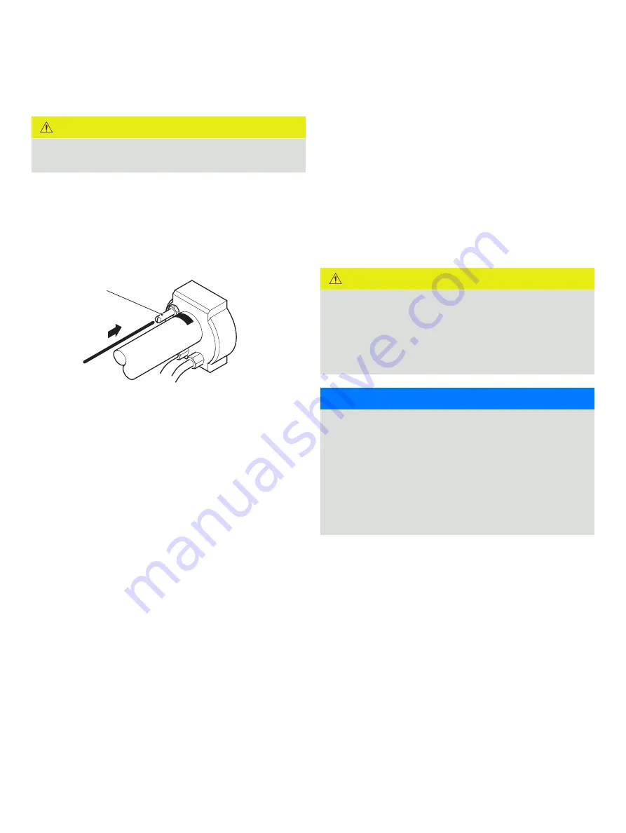
The sensor has one test gas inlet – see Figure 21. A flowmeter 
must be fitted to the test gas line to restrict/regulate the flow. 
The pressure is set to 1 bar (15 psi) then flow is restricted by the 
flowmeter.

Refer to page 25 topage 28 for pneumatic entry types.

Figure 21  AZ10 probe – test gas connection

Test gas inlet

The sensor test gas (calibration) inlet is provided for in situ 
sensor testing using a test gas.

If the sensor is connected permanently to the test gas supply 
pipework:

•  fit a high quality, corrosion-resistant (stainless steel), 

solenoid valve, manually operated valve or non-return valve 
(that is leak-tight even at zero back-pressure) in the 
pipework, as close to the test gas inlet valve as possible

•  keep the valve closed when the calibration system is not  

in use

 CAUTION

If the test gas connection is not sealed when not in use, air 
leaking into the sensor via the connection causes 
measurement errors. In a pressurized process, gases 
venting to atmosphere through the connection cause 
corrosion of, and/or block, the test gas tube. In a negative 
pressure process, air leakage causes high O2 reading errors.

NOTICE

•  It is preferable to use air (20.95 % O2) as one of the test 

gases as this is the sensor’s zero point. Alternative 
representative gases can be used according to local 
environmental conditions. 

•  To ensure better accuracy, use 2 test gases that represent 

the top and bottom limits of the known operating range.

•  Due to resolution accuracies, do not calibrate the system 

with gases of less than 1 % O2.

Summary of Contents for Endura AZ10

Page 1: ...tenance free operation The modular design with reduced component count improves the reliability and robustness of the system and simplifies breakdown repair if it occurs Kits containing all the parts...

Page 2: ...s 17 EMC cable gland 17 Cable preparation non AutoCal systems both ends AZ10 probe to AZ10 transmitter 18 Cable preparation AutoCal systems both ends AZ10 probe to AZ10 AutoCal unit 20 Electrical conn...

Page 3: ...must be stored away from heat protected from temperature extremes and powders kept dry Normal safe handling procedures must be used When disposing of chemicals ensure that no two chemicals are mixed S...

Page 4: ...ies with US NEC 500 NIST and OSHA Product symbols Symbols that appear on this product are shown below Protective earth ground terminal Functional earth ground terminal This symbol when noted on a prod...

Page 5: ...modifying system parameters Install and use this equipment as detailed in this guide Install and use associated equipment in accordance with the relevant national and local standards The AZ10 oxygen p...

Page 6: ...a cell if the process is cleaned using water If this method of cleaning is employed remove the probe from the process prior to cleaning Unpacking CAUTION Visually inspect equipment for damage after un...

Page 7: ...70 C 4 to 158 F CAUTION Do not exceed the probe terminal head maximum operating temperature The probe must be sited in an area where radiated heat from the process does not cause the maximum temperatu...

Page 8: ...nges see page 9 270 10 63 34 1 34 100 sq 3 93 13 0 5 127 5 0 1 25 in NPS SCH5 42 16 mm 95 3 7 202 81 standard gland 98 3 9 150 5 9 R3 2 0 1 179 7 0 71 2 8 135 5 3 R39 1 5 203 8 0 125 4 9 303 11 9 8 5...

Page 9: ...80 PN16 200 7 87 12 0 47 18 0 70 160 6 30 B A C D Figure 4 8 Hole probe flange types and dimensions Flange type A B C D E F G PCD 2 in NPT 48 1 88 20 0 79 48 1 89 2 in thread 100 8 3 96 100 8 3 96 80...

Page 10: ...5 Duct surface temperature 400 C 752 F max If the flue is lagged a stand off tube of suitable length with a minimum internal diameter of 55 mm 2 16 in may be used Do not mount the probe in such a mann...

Page 11: ...e concentric with the hole in the flue 3 Apply high temperature jointing compound to the threads C of the probe mount adaptor and screw the adaptor into the boss 4 Locate a gasket D over the studs on...

Page 12: ...lue wall B 2 Weld a mounting plate AZ1000098 C into place concentric with the hole in the flue 3 Locate a gasket D over the studs on the adaptor see Note left 4 Insert the probe intake tube E through...

Page 13: ...AZ10 OXYGEN ANALYZER COMBUSTION GAS ANALYSIS OI AZ10 EN REV A 13 Figure 9 ABB standard flange mounting plate Gas flow Exit...

Page 14: ...Fit a suitable mating flange customer supplied A to the flue wall 2 Secure flange B to the flue mounted mating flange A using suitable fixings C not supplied 3 Locate a gasket D over the studs on flan...

Page 15: ...AZ10 OXYGEN ANALYZER COMBUSTION GAS ANALYSIS OI AZ10 EN REV A 15 Figure 10 Flange mounted installations Gas flow Exit...

Page 16: ...basic insulation After installation there must be no access to live parts for example terminals Terminals for external circuits are for use only with equipment with no accessible live parts If the equ...

Page 17: ...tems probe to AutoCal unit and AutoCal unit to transmitter maximum combined length 100 m 300 ft Refer to the following pages for connection requirements page 19 for non AutoCal systems probe to transm...

Page 18: ...wist Screen 1 and Screen 2 drain wires together to form a twisted pair at each end of the cable and fit a 40 mm 1 57 in earth sleeve not supplied over each twisted pair 6 Cut back all unused wires as...

Page 19: ...e Blue cut wires back both ends White Yellow White Black White Orange White Green White Red White Blue Not fitted Not applicable Table 1 Cable requirements non AutoCal systems AZ10 probe to AZ10 trans...

Page 20: ...een 1 and Screen 2 drain wires together to form a twisted pair at each end of the cable and fit a 40 mm 1 57 in earth sleeve not supplied over each twisted pair 6 Cut back all unused wires as instruct...

Page 21: ...cut wire back both ends White Red cut wire back both ends White Blue cut wire back both ends White Yellow White Black White Orange White Green White Red White Blue N A Not used Table 2 Cable requirem...

Page 22: ...m a twisted pair at each end of the cable and fit a 40 mm 1 57 in earth sleeve not supplied over each twisted pair 6 Cut the insulation back on each of the remaining wires to expose 10 mm 0 4in of wir...

Page 23: ...Red White Blue White Yellow White Black White Orange White Green White Red White Blue PS2 test gas 2 P Comm PS1 test gas 1 SV2 SV Comm SV1 Cable requirements AZ10 AutoCal unit to AZ10 transmitter Auto...

Page 24: ...ss steel solenoid valve manually operated valve or non return valve that is leak tight even at zero back pressure in the pipework as close to the test gas inlet valve as possible keep the valve closed...

Page 25: ...ply non AutoCal system air test gas 1 and optional bottled gas test gas 2 System using 2 bottled test gases Figure 23 Test gas supply non AutoCal system 2 bottled test gases AZ10 probe Shut off valve...

Page 26: ...rom AutoCal VENT connection to test gas inlet at probe 14 core screened AutoCal unit to probe length coded option ABB 14 core cable transmitter to AutoCal unit length coded option Test gas 2 in Cable...

Page 27: ...supply restrictor in Autocal unit limits flow to 2 2 l min 4 662 scfh at 1 bar 15 psi Test gas 1 1 bar 15 psi Test gas port 5 m oil coalescing filter regulator Test gas 2 optional from bottled gas adj...

Page 28: ...t Test gas supply 1 l min 2 118 scfh Test gas 1 ABB flowmeter adjusted to 1 l min 2 118 scfh STP ABB flowmeter adjusted to 1 l min 2 118 scfh STP 5 m oil coalescing filter regulator Test gas 2 optiona...

Page 29: ...y is fitted securely to the test gas inlet connection on the sensor 2 If the sensor is connected permanently to test gas pipework ensure that a valve is installed in the pipework adjacent to the test...

Page 30: ...pprovals and safety certification CE mark 11 Probe specification Physical Process connection ANSI B16 5 150 lb 2 5 3 in DIN2501 Part 1 65 80 mm 2 in NPT 2 in BSP flange pressure ratings do not apply A...

Page 31: ...rable can be activated by one or more of the following signals Process alarm 1 2 3 4 Calibration in progress Calibration failed Out of test gas 1 2 Test gas 1 valve control Test gas 2 valve control Fa...

Page 32: ...itch is open selects 1 point low level volt free switch is closed selects 2 point Output functions Process alarm 1 2 3 4 Calibration in progress Calibration failed Out of test gas 1 Out of test gas 2...

Page 33: ...e CSA approved 5 m 16 4 ft 10 m 32 8 ft 25 m 49 2 ft 50 m 164 0 ft 75 m 213 2 ft 100 m 328 0 ft AZ100078 AZ100079 AZ100080 AZ100081 Sample guide tube 200 mm 9 84 in 350 mm 15 75 in 500 mm 21 65 in 650...

Page 34: ...analog O P Standard digital O P AZ200758 Remote type 4 transmitter backplane AZ200724 Probe heater circuit fuse AZ200725 PT1000 cold junction compensation AZ100056 Cell assembly kit AZ100065 Seals an...

Page 35: ...AZ10 OXYGEN ANALYZER COMBUSTION GAS ANALYSIS OI AZ10 EN REV A 35 Acknowledgments HART is a registered trademark of the FieldComm Group Sales Service Software...

Page 36: ...ghts in this document and in the subject matter and illustrations contained therein Any reproduction disclosure to third parties or utilization of its contents in whole or in parts is forbidden withou...

Reviews: