background image

Endura AZ series integral and remote transmitter

Combustion oxygen monitor

8 Troubleshooting

IM/AZ20E–EN Rev. F

89

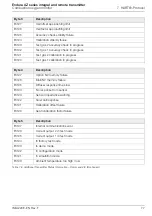
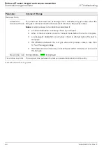
8.3.2 Performance Log Codes

Parameter

Comment / Range

Type

The calibration type, represented as an icon – see Table 8.6, page 88:

Calibration

Failed Cal

Accuracy Check

Failed Accuracy Check

New Probe 

Time and Date of 
Entry

The time and date the calibration / accuracy check was performed or the new
probe / cell was fitted.

Calibration Offset

The calculated calibration offset value displayed as a mV value.

Calibration Factor 

The calculated calibration factor value.

Deviation

Calibration

The difference between the oxygen value as it is being calculated with the
newly-updated coefficients 

and

the oxygen value as it would have been calculated with the coefficients used
before the calibration was performed.

Accuracy Check The  difference  between the oxygen value as it would be calculated using the

coefficients calculated by the accuracy check 

and

the oxygen value as it is being calculated with the existing coefficients.

New probe / cell  Not applicable – 

 is displayed

Table 8.8 Performance Log Fields

Summary of Contents for Endura AZ series

Page 1: ...ding for combustion control optimization and emissions monitoring For more information Further publications for the Endura AZ series analyzers are available for free download from www abb com measurement or by scanning this code Search for or click on Data sheet Endura AZ20 oxygen monitor Combustion gas analysis DS AZ20 EN Data sheet Endura AZ25 oxygen analyzer Combustion gas analysis DS AZ25 EN M...

Page 2: ...tion Key 1 1 Pt and 2 Pt AutoCal options displayed only if AutoCal hardware is fitted 2 Not displayed when Autocal Hardware Hardware Type is set to None 3 Displayed only at Advanced level access Refer to Section 5 4 2 page 36 Refer to Section 5 4 3 page 44 Refer to Section 5 4 4 page 45 Display see inside back cover ...

Page 3: ...ransmitter Access to Terminals 13 4 3 Remote Transmitter Cable Gland Entries and Main Board Connections 14 4 4 Remote Transmitter Remote AZ10 Sensor Cable Connections 15 4 4 1 Systems with 5 m 18 ft Cable Length 15 4 4 2 Systems with 5 m 18 ft Cable Length 16 4 5 Remote Transmitter Remote AZ20 Probe Cable Connections 17 4 6 Remote Transmitter Remote AZ25 Probe Connections 18 4 7 Remote Transmitter...

Page 4: ... Byte 74 7 5 2 Field Device Status Second Byte 75 7 5 3 Additional Transmitter Status Information Command 48 76 8 Troubleshooting 78 8 1 Diagnostics Classification Codes 78 8 2 Diagnostics Messages 79 8 2 1 Failure Messages 79 8 2 2 Out of Specification Messages 82 8 2 3 Maintenance Messages 84 8 2 4 Check Function Messages 86 8 3 Performance Log 88 8 3 1 Log Entries 88 8 3 2 Performance Log Codes...

Page 5: ...ur products are safe and without risk to health the following points must be noted The relevant sections of these instructions must be read carefully before proceeding Warning labels on containers and packages must be observed Installation operation maintenance and servicing must only be carried out by suitably trained personnel and in accordance with the information given Normal safety precaution...

Page 6: ...should handle chemicals or perform maintenance on chemical delivery systems associated with the equipment This symbol indicates the need for protective eye wear This symbol indicates the need for protective hand wear Electrical equipment marked with this symbol may not be disposed of in European public disposal systems In conformity with European local and national regulations European electrical ...

Page 7: ...lar attention to all warning and caution statements Failure to do so could result in serious injury to the operator or damage to the equipment To ensure the protection provided by this equipment is not impaired do not use or install this equipment in any manner other than that which is specified in this manual Note The following only applies to European customers ABB is committed to ensuring that ...

Page 8: ...lems with installation starting or using the instrument please contact the company that sold it to you If this is not possible or if the results of this approach are not satisfactory please contact the manufacturer s Customer Service 1 12 Potential Safety Hazards The following potential safety hazards are associated with operating the system Electrical line voltage Potentially hazardous chemicals ...

Page 9: ...here within the transmitter s display range of 0 to 100 O2 Remote alarm indication is provided by two relay outputs Relays are programmed to activate when the oxygen level moves either above or below a pre defined set point The alarm relay can also be used as a general alarm that is activated in the event of a transmitter or system fault This User Guide provides the following information installat...

Page 10: ...due harm to the environment and must be disposed of in accordance with the Directive on Waste Electrical and Electronic Equipment WEEE It must not be disposed of in Municipal Waste Collection 3 3 Cleaning The transmitter can be hosed down if it has been installed to IP66 NEMA 4 standards cable glands are fitted correctly and all unused cable entry holes are blanked off see Section 4 1 1 page 12 re...

Page 11: ...mitter in a position where its temperature and humidity specification are not exceeded and ensure it is protected from direct sunlight rain snow and hail Select a location away from strong electrical and magnetic fields If this is not possible particularly in applications where mobile communications equipment is expected to be used screened cables within flexible earthed metal conduit must be used...

Page 12: ...emote Transmitter Dimensions Fix remote transmitter to a secure surface using 3 x M5 screws not supplied 3 5 2 Probe Dimensions Refer to IM AZ20P EN for probe and integral system dimensions Dimensions in mm ft Fig 3 3 Remote Transmitter Dimensions Standard Glands Shown 202 8 Standard Glands 250 9 8 Armored Glands 98 3 9 R3 2 0 1 71 2 8 179 7 0 150 5 9 ...

Page 13: ...t conforms to Installation Category II of IEC 61010 All connections to secondary circuits must have basic insulation After installation there must be no access to live parts for example terminals Terminals for external circuits are for use only with equipment with no accessible live parts If the equipment is used in a manner not specified by the Company the protection provided by the equipment may...

Page 14: ...ctrical Installation 12 IM AZ20E EN Rev F 4 1 1 AC Power Supply Connections Note Tighten power supply terminal screws to a torque of 0 8 Nm 7 lbf in Fig 4 1 AC Power Supply Connections L N 1 2 3 Warning Use fuse rated 1 6 A Type F only Fuse Line Neutral 100 to 240 V AC 10 50 60 Hz ...

Page 15: ... access them by gently pulling the rotation lock D back and rotating the cartridge E until the cartridge screw access holes align with the cartridge screw heads 5 Slacken the three cartridge screws and lift the cartridge F away from the housing 6 To refit the cover reverse the actions in steps 1 to 5 Warning Isolate the transmitter from power supplies before removing the cover Fig 4 2 Accessing Re...

Page 16: ...ntries and Main Board Connections Fig 4 3 Cable Gland Conduit Entries Remote Transmitter and Main Board Power Cable Gland Relay Output Gland External Earth Probe Cable Gland Probe Cable Terminals Output Terminals Relay Terminal Fuse Anti tamper seal Anti tamper seal Internal Earth Alternative Protective Earth Output Connections Gland AC Power Supply Terminal ...

Page 17: ...ck Black Cell oxygen input Violet Violet Violet ACJC Grey Grey Grey ACJC Green Green Green T C White White White T C Earth stud Screen 1 and 2 SCN not used Screen 1 and 2 sleeved See Fig 4 4 Brown Brown Brown Heater 1 Blue Blue Blue Heater 2 Table 4 1 Systems with 5 m 18 ft Cable Length Fig 4 4 Systems with 5 m 18 ft Cable Length VIOLET BLACK RED WHITE CELL GREY GREEN T C ACJC CELL T C R W BL BLUE...

Page 18: ... ACJC Grey Grey Grey ACJC Green Green Green T C White White White T C Earth stud Screen 1 and 2 SCN Screen 1 and 2 Screen 1 and 2 sleeved drains See Fig 4 5 Brown Brown Brown Heater 1 Blue Blue Blue Heater 2 Table 4 2 Systems with 5 m 18 ft Cable Length Fig 4 5 Systems with 5 m 18 ft Cable Length VIOLET BLACK RED WHITE CELL GREY GREEN T C ACJC CELL T C R W BL BLUE BROWN GREEN H1 CLR CLR H2 H1 H2 A...

Page 19: ...Input ve Black 9 CELL Oxygen Input ve Red 10 PS2 Pressure Switch Gas 2 White Yellow 11 P COM Pressure Switch Common White Black 12 PS1 Pressure Switch Gas 1 White Orange 13 SV2 Solenoid Valve Gas 2 White Blue 14 SV COM Solenoid Valve Common White Red 15 SV1 Solenoid Valve Gas 1 White Green Table 4 3 Remote Transmitter Remote AZ20 Probe Cable Connections Fig 4 6 Remote Transmitter Remote AZ20 Probe...

Page 20: ...e cable wire colors Probe remote transmitter connection Green Green TC White White TC Red Red Cell Black Black Cell Orange Orange ACJC Blue Blue ACJC SCN not used see Fig 4 7 sensor cable screen drain connected at transmitter internal earth stud only Screen drain see Fig 4 7 for sensor cable screen connections Screen drain see Fig 4 7 for screen connection at transmitter Table 4 4 Remote Transmitt...

Page 21: ...robe Connections Endura AZ25 probe Factory made connections at probe inner terminal connectors Factory made connections Endura AZ25 remote transmitter Screen drain of 6 core sensor cable at Endura AZ25 probe cut back and isolated Connect drain at Endura AZ25 transmitter end to transmitter internal earth stud only Cell Red Cell Black ACJC Orange ACJC Blue T C Green T C White NOT USED SCN Screen Ter...

Page 22: ...CELL Oxygen Input ve Red 10 PS2 Pressure Switch Gas 2 White Yellow 11 P COM Pressure Switch Common White Black 12 PS1 Pressure Switch Gas 1 White Orange 13 SV2 Solenoid Valve Gas 2 White Blue 14 SV COM Solenoid Valve Common White Red 15 SV1 Solenoid Valve Gas 1 White Green Table 4 5 Remote Transmitter to Remote AZ25 AutoCal Unit Connections Fig 4 8 Remote Transmitter to Remote AZ25 AutoCal Unit Co...

Page 23: ...connections to the relay outputs terminal block B and current output and option board terminals terminal block G as required 5 Refit the transmitter front cover see Section 4 2 page 13 Warning The transmitter must be earthed Isolate the incoming mains power supply cable before making connections at the transmitter or the probe Fig 4 9 Remote Transmitter Power Supply and Output Connections C B A C ...

Page 24: ... socket 5 Referring to Section 4 2 page 13 refit the transmitter front cover and cartridge 4 9 Integral Transmitter Access to Connections Referring to Fig 4 11 1 Unscrew and remove the transmitter rear cover A 2 Access power supply terminals by unclipping latch B and lifting hinged power supply cover C Note The internal fuse is a protection device for the probe heater it is not a transmitter mains...

Page 25: ...pensation White Blue SV2 Solenoid Valve Gas 2 White Red SV COM Solenoid Valve Common White Green SV1 Solenoid Valve Gas 1 White Orange PS1 Pressure Switch Gas 1 White Black P COM Pressure Switch Common White Yellow PS2 Pressure Switch Gas 2 Table 4 6 Probe Cable Connections at Integral Transmitter Fig 4 12 Probe Cable Connections at Integral Transmitter H Blue H Brown Cell Red Cell Black TC Green ...

Page 26: ... cover see Fig 4 11 5 Feed the signal cable s through cable gland s D and make connections to the relay output s current output and option terminals as required 6 Refit the rear cover see Fig 4 11 and tighten it hand tight Warning The transmitter must be earthed Isolate the incoming mains power supply cable before making connections at the transmitter Fig 4 13 Integral Transmitter Power Supply and...

Page 27: ... screw A 3 Unscrew and remove lid B 4 Slacken the three cartridge screws C and lift the cartridge D away from the housing 5 Remove the plug in fuse E from the fuse socket and plug a new fuse 1 A type F into the fuse socket 6 Refit the cartridge and lid by reversing steps 4 to 1 Note The internal fuse is a protection device for the probe heater it is not an integral transmitter mains power isolatio...

Page 28: ...n A Screen title at the current level parameter B Menu level title C Menu level icon D Prompt executed by pressing the key E Prompt executed by pressing the key F Left key used for parameter navigation back to previous screen G Up Down keys used to scroll through menu options and to increase decrease values in editable parameters H Right key used to navigate to sub levels and to accept select para...

Page 29: ...5 4 5 page 48 In addition to any status icons displayed see Section 8 1 page 78 the following icons are displayed on at the bottom of each page Operator Menu icon always displayed Access Level icon always displayed Autoscroll icon displayed when Autoscroll is enabled at the Display Autoscroll parameter see page 51 Locked icon displayed when access to menus is denied due to a time out or attempting...

Page 30: ... pages are available Operator Page 1 is always enabled Operator Page 2 can be set to OFF or enabled When Operator Page 2 is enabled it is listed in the Operator Menu Setup of the two Operator pages is performed at the Display menu by selecting pre configured display options see Section 5 4 5 page 48 Autoscroll When enabled the 2 Operator pages 1 and 2 are toggled at 10 second intervals providing o...

Page 31: ... Cell Temperature Rate of Rise of Cell Temperature Cell Millivolts Heater Output Cold Junction Temp Calibration Offset Calibration Factor Cell Zero Offset O2 Deviation Cell Impedance Cell Impedance Drift Test Gas Response Time Recovery Rate Mains Voltage Mains Frequency Internal Temperature 0 01 to 100 00 O2 700 C 1292 F After stabilization phase 0 to 60 C min 0 to 108 F min 50 to 190 mV 0 to 100 ...

Page 32: ...er Password screen Advanced users have full end user configuration privileges to set and change passwords for Standard and Advanced level users Each password can comprise up to 6 alphanumeric characters selectable from the Enter Password screen see page 31 and any mix of letters or digits Note During manufacture Standard and Advanced level passwords are left unset and must be user allocated as req...

Page 33: ...ected levels Enter Password At the Enter Password screen use the and keys to navigate to individual password character s Press to select a password character When all password characters have been selected press If the password is correct the requested level is accessed If the password is incorrect the last viewed Operator Page is displayed with the Locked icon in the status bar Note A default tim...

Page 34: ...ion 5 4 1 page 33 Refer to Section 5 4 2 page 36 Refer to Section 5 4 6 page 53 Refer to Section 5 4 3 page 44 Refer to Section 5 4 7 page 54 Refer to Section 5 4 4 page 45 Refer to Section 5 4 8 page 61 Refer to Section 5 4 5 page 48 Refer to Section 5 4 9 page 63 Table 5 5 Overview of Operating Menus 1 Menu Exit Select Easy Setup 2 Menu Exit Select Calibrate 6 Menu Exit Select Process Alarm 3 12...

Page 35: ...8 Characters are selected from an alphanumeric list see Section 5 1 page 26 for navigation details The tag is not displayed on the Operator Page s if a Display Mode of 3 x 9 is selected see Section 5 4 5 page 48 N A Date Format Selects the format of the displayed date DD MM YYYY MM DD YYYY YYYY MM DD YYYY MM DD Time Date Sets the current local time and date N A Hr Min Sec Year Month Day Probe Type...

Page 36: ... Select this option if an external automatic calibration system is to be used Note The solenoid valve outputs or relays can be used to activate a remote automatic calibration system O2 Range Hi Sets the maximum oxygen concentration 0 01 to 100 O2 25 00 O2 O2 Range Lo Sets the minimum oxygen concentration 0 01 to 100 O2 0 01 O2 Thermocouple Type Selects the thermocouple type used for cell temperatu...

Page 37: ...0 10 mV non AZ10 0 mV Note Refer to the label supplied with cell Factory Cal Factor Used to enter the calibration factor value supplied with the new probe cell Note Refer to the label supplied with cell 1 00 New Probe Cell Fitted Used to confirm and setup a new probe or cell Select OK to confirm a new probe or cell has been fitted this resets the diagnostic measurements and states A new entry is c...

Page 38: ...AutoCal Performs a single point automatic calibration Enabled only if calibration is currently inactive Autocal is fitted and temperature has stabilized 2 Pt AutoCal Performs a two point automatic calibration Enabled only if calibration is currently inactive Autocal is fitted and temperature has stabilized Manual Cal Offset Performs a manual single point offset calibration Enabled only if calibrat...

Page 39: ... Process Air The atmospheric air within the flue surrounding the probe used to calibrate the system Test Gas 2 Value Enabled when Test Gas 2 Type is set to Gas 0 01 to 100 00 O2 1 00 O2 Oxygen Hold During O2 calibrations the O2 value displayed on the local HMI human machine interface is set according to the Action selected below This value is also retransmitted as current outputs and transmitted v...

Page 40: ...the probe Note For use with remote automatic calibration units only 0 to 9999 s 0 Test Gas Detection The probe s internal automatic calibration system has pressure switches to detect the presence of the test gases automatically when enabled This option can also be used with remote automatic calibration units with suitable pressure switches Test Gas 1 Detection Disabled if AutoCal Hardware Hardware...

Page 41: ...ardware Type is set to None Closed Test Gas 2 Valve Disabled if AutoCal Hardware Hardware Type is set to None Closed Scheduled Cal If AutoCal is fitted automatic calibrations can be set to run at scheduled time intervals Note This option is not available if the AutoCal Hardware Hardware Type is set to None Type Selects the scheduled calibration type One point Offset only calibration Two point Offs...

Page 42: ...ily interval for scheduled automatic calibrations of the probe Enabled when Frequency is set to Daily Daily Daily 2 3 4 5 6 7 Days Weekly Interval Sets the required weekly interval for scheduled automatic calibrations of the probe Enabled when Frequency is set to Weekly Weekly Weekly 2 3 4 6 13 26 52 Weeks Monthly Interval Sets the required monthly interval for scheduled automatic calibrations of ...

Page 43: ...bration date is updated according to the frequency set and an Out of Specification Missed Scheduled AutoCal diagnostic message is created see Section 8 2 2 page 82 N A Sequence Selects the type of calibration check to be performed Calibration Performs a calibration that automatically updates the calibration offset and factor if successful Calibration Accuracy check Performs an accuracy check this ...

Page 44: ...deal probe has an offset of 0 mV The limit is a deviation from the ideal for example if 10 mV is set the calibration offset has an acceptable range of 10 to 10 mV 0 00 to 20 00 mV 20 00 mV Factor Limit An ideal probe has a factor of 1 000 The limit is a deviation from the ideal for example if 0 100 is set the calibration factor has an acceptable range of 0 900 to 1 100 0 000 to 0 100 0 100 Cell Di...

Page 45: ...imit Sets the limit to be used with the slow recovery rate diagnostic function 0 1 to 10 0 O2 s 10 0 O2 s High Impedance Diag Warns if the cell s impedance goes above a preset limit a high impedance can indicate a faulty or ageing cell Disabled Disabled Enabled Performs an impedance check when a Two point calibration is selected see page 39 Measure Impedance With a stable output from the cell a ce...

Page 46: ... of occurrences total duration and time since the last occurrence Data is displayed in the following format n number of instances of the diagnostic state t total time spent in this diagnostic condition tn time since last instance of this diagnostic condition Note Use the and keys to scroll through the list of alarms Clear History Clears the saved diagnostic history log Performance Log A time and d...

Page 47: ...ected from an alphanumeric list The Instrument Tag is not displayed in the Operator page s when a Display Mode of 3 x 9 is selected see Section 5 4 5 page 48 N A Probe Type Selects the probe type to be used with the transmitter AZ20 Remote Tx AZ20 Remote Tx AZ20 Integral Tx AZ25 Remote Tx AZ30 Integral Tx AZ30 Remote Tx AZ35 Remote Tx AZ10 With Filter AZ10 No Filter Cable Length The length in metr...

Page 48: ...ct to the pressure during a calibration is present If calibrations are performed at the same pressure as normal operation set this value to 0 00 psi 5 00 to 5 00 psi 0 00 psi Temp Setup Selects thermocouple type and temperature units Thermocouple Type Selects the thermocouple type used for cell temperature measurement For heated probes AZ20 and AZ30 this is fixed as type K For unheated probes AZ25...

Page 49: ...n parameters to their default values Factory set Reset Temp Trip For heated probes AZ20 and AZ30 if the cell temperature exceeds a preset limit approx 850 C 1562 F a hardware over temperature trip automatically activates and switches off power to the heater If the cell temperature remains at this elevated temperature for less than 30 minutes the trip is reset automatically If the elevated temperat...

Page 50: ...añol Italiano Operator Page 1 Specifies the type of information to be displayed on each text line Display Mode Selects the number of lines of information and maximum number of characters per line displayed on the selected Operator page Note The instrument ID tag if added is displayed in the operator page except when the 3 x 9 format is selected 1 x 4 Displays 1 line with up to 4 characters 1 x 4 1...

Page 51: ...ll Temperature Cell Millivolts Control Output 3rd Line View Cell Temperature Cell Millivolts Cell Millivolts Control Output Bargraph Specifies the parameter represented on the bargraph Note Available only when Display Mode is set to 1 x 6 Bargraph or 2 x 9 Bargraph see page 48 Control Output Oxygen linear Oxygen linear Oxygen log Parameter Comment Range Default Table 5 10 Display Menu Continued ...

Page 52: ...e 3 x 9 format is selected see page 48 Off Disables Operator Page 2 Off 1 x 4 Displays 1 line with up to 4 characters 1 x 6 Displays 1 line with up to 6 characters 1 x 6 Bargraph Displays 1 line with up to 6 characters plus bargraph 2 x 9 Displays 2 lines each with up to 9 characters 2 x 9 Bargraph Displays 2 lines each with up to 9 characters plus bargraph 3 x 9 Displays 3 lines each with up to 9...

Page 53: ... to 1 x 6 Bargraph or 2 x 9 Bargraph see page 48 Control Output Oxygen linear Oxygen linear Oxygen log Autoscroll Disabled Enabled When Enabled the display toggles automatically between Operator Page 1 and Operator Page 2 at 10 second intervals If enabled here it can be disabled in the Operator level Enabled Time Date Sets the date format and the time date Format DD MM YYYY MM DD YYYY YYYY MM DD Y...

Page 54: ...er than Europe or USA Note Enables Daylight Start and Daylight End parameters Daylight Start Daylight End Sets the Daylight Saving start and end criteria Note Displayed only when the Region sub parameter is Custom N A Time Start time selected in 1 hour increments 00 00 to 23 00 Occurrence First Second Third Fourth Last Day Sunday Monday Tuesday Wednesday Thursday Friday Saturday Month January Febr...

Page 55: ...Low Oxygen High Oxygen Low Temperature High Temperature Trip Sets the alarm trip value in engineering units see Fig 5 2 Note One trip value can be set for each alarm Oxygen 0 01 to 100 00 O2 1 00 O2 Temperature 300 to 1800 C 508 to 3272 F 720 C Hysteresis Sets the hysteresis value in engineering units see Fig 5 2 Oxygen 0 00 to 100 00 O2 0 O2 Temperature 0 to 1000 C 32 to 1832 F 0 C Table 5 11 Pro...

Page 56: ...ted when a calibration is in progress Cal Failed Relay is activated if a calibration fails Gas 1 Not Present Relay is activated if test gas 1 is not detected Gas 2 Not Present Relay is activated if test gas 2 is not detected Test Gas 1 Valve Relay is activated if test gas 1 valve is open Test Gas 2 Valve Relay is activated if test gas 2 valve is open Diag Failure Activates the relay if a Failure d...

Page 57: ...nput Output Output Assignment If the Digital I O Mode is Output selects which alarm and diagnostic states are required to energize the output Each Output Assignment parameter can be Assigned or Not Assigned Note Assigned parameters are OR d together Not Assigned all parameters Alarm 1 2 3 4 See Section 5 4 6 page 53 for alarm details Cal In Progress Output is triggered when a calibration is in pro...

Page 58: ...e assigned states are active Active High Active High Active Low Input Function If the Digital I O Mode is Input selects the function to be performed by the digital input Off Off Start Autocal Starts automatic calibration on falling edge when a voltage free switch is closed Stop Autocal Stops automatic calibration on falling edge when a voltage free switch is closed Start Stop Autocal Starts automa...

Page 59: ...ibration Performs a calibration that updates the calibration offset and factor automatically if successful Accuracy Check Performs an accuracy check the normal calibration sequence but does not update the calibration offset and factor in use by the transmitter Cal On Error Limit Performs an accuracy check but if the error is greater than the value set in the Cal Error Limit field see page 41 the c...

Page 60: ...ear Log Two Decades Log Three Decades Eng Range Hi Selects an engineering range high value depending on the option selected in Source Oxygen 0 00 to 100 00 O2 25 00 O2 Temperature 200 to 1800 C 328 to 3272 F mV 100 0 to 400 0 mV Eng Range Lo Selects an engineering range low value depending on the option selected in Source Note Not enabled if Type Log Two Decades or Log Three Decades Oxygen 0 00 to...

Page 61: ...rrent output can be driven to a preset value if a Failure category diagnostic state occurs see page 78 Disabled Enabled Disabled Failure Current Sets a preset value that the current output is driven to when a Failure category diagnostic state is present see page 78 Available only if Output Failure is Enabled 3 80 to 22 0 mA 22 00 mA Output 1 Test Selects output levels for Current Output 1 When thi...

Page 62: ...n Enabled the current output can be driven to a preset value if a Failure category diagnostic state occurs see Section 8 1 page 78 Disabled Enabled Disabled Failure Current Sets a preset value that the current output is driven to when a Failure category diagnostic state is present see page 78 Only available if Output Failure is Enabled 0 00 to 22 0 mA 22 00 mA Output 2 Test Selects output levels f...

Page 63: ...ce ID The unique ID for the HART device Factory set read only ID HART Tag Used to enter a user defined tag for the HART device transmitter selected from the alphanumeric character set displayed when the Edit button is selected at this sub parameter 0 to 8 characters N A HART Device Message Used to specify a a user defined message for the HART device transmitter selected from the character set disp...

Page 64: ...ransmitter these can be viewed via hyperterminal Interval Selects the time interval between each set of data to be sent out via IrDA Off Off 1 10 30 s 1 10 30 60 m Assignment Selects which signals are to be transmitted Assigned Not Assigned Not Assigned all parameters Oxygen Cell Temperature Cell Temp Rate Cell mV Output CJ Temperature Cal Details Performance Details Mains Supply Details Internal ...

Page 65: ...r N A Probe Type The probe type used with the transmitter AZ20 Integral Tx AZ20 Remote Tx AZ25 Remote Tx AZ30 Integral Tx AZ30 Remote Tx AZ35 Remote Tx AZ10 With Filter AZ10 No Filter AZ20 Remote Tx Autocal Hardware The automatic calibration system configured for use with the transmitter None Disables automatic calibration functions None Internal Enabled if the optional built in automatic calibrat...

Page 66: ...ibration Offset and Calibration Factor Performs slope and offset calibration using both test gases Manual Cal Offset Single point manual calibration of Calibration Offset The values of the two test gases are compared and an offset calibration is performed using whichever test gas is closest to air 20 95 If the values of the two test gases are equal test gas 1 is used Manual Cal Factor Single point...

Page 67: ...plicable if the Test Gas Type is Process Air see page 37 Test Gas Response Time monitored if no response to the application of the test gas is detected the test gas valve is closed and the calibration fails At this point the calibration procedure remains idle while the test gas delay timer runs AutoCal only Oxygen value is monitored for stability if the stability criteria are not met the test gas ...

Page 68: ...est gas valve is closed and the calibration fails At this point the calibration procedure remains idle while the test gas delay timer runs AutoCal only Oxygen value is monitored for stability if the stability criteria are not met the test gas valve is closed and the calibration fails Once the stability criteria have been met a cell impedance check is performed and the test gas valve is closed Once...

Page 69: ...al Cal Factor Manual Cal 2 Pt Return to Sensor Cal Calibration failed to complete The reason for failure is displayed stability criteria not met no response to the application of a test gas detected calibration successful but Save of new calibration factor unsuccessful newly calculated calibration factor is outside the limits defined by Factor Limit and or the newly calculated calibration offset i...

Page 70: ...C using a USB or RS232C connector Alternatively a hand held terminal can be used see below Compatible Management Software Management software required to communicate with HART compatible devices using Universal and Common Practice commands Hand held Terminal The transmitter can be accessed and configured using a compatible hand held terminal such as the ABB Mobility DHH801 MFC or equivalent see Fi...

Page 71: ...The HART Protocol is also available optically via the IrDA interface on the front of the transmitter Fig 7 1 HART Protocol Connection Remote Installation Shown Hand held Terminal for example ABB Mobility DHH801 MFC 4 mA Current Output Multidrop Connection 4 to 20 mA Current Output Single Connection PC Connection USB or RS232 Multidrop Connection Probe 250 Minimum Load Single Connection HART Connec...

Page 72: ...y Variable Oxygen value 2 Read Current and Percent of Range PV Oxygen as current output mA PV Oxygen as percentage of range 3 Read Dynamic Variables and Current Current output value mA Oxygen value Cell Temperature o C or o F Cell Millivolts 6 Write Polling Address When set to 0 Current Output 1 is active and provides an analog output proportional to its source HART operates in point to point mode...

Page 73: ...RT write protection code Any private label distributor code associated with the transmitter 16 Read Final Assembly Number Returns the user defined final assembly number Number can also be viewed via Communications menu on the device s local HMI 17 Write Message Enables a user defined message of up to 32 characters to be entered Message can also be entered via the Communications menu on the device ...

Page 74: ...viation 11 Cell calibration offset 12 Cell calibration factor 13 Cell zero offset 14 Mains frequency 15 Mains voltage 34 Write Primary Variable Damping Value Sets the filter value for the Oxygen reading 35 Write Primary Variable Range Values Sets the Oxygen range hi and lo values 38 Reset Configuration Changed Flag Bit 6 Configuration Changed of the Transmitter Status Byte is reset by this command...

Page 75: ... indicates there is additional status information it can be obtained via this command 49 Write Primary Variable Sensor Serial Number Enables a transducer serial number to be entered 60 Read Analog Channel and Percent of Range Returns the current mA value on Current Output 2 and that value as a percentage of its range 66 Enter Exit Fixed Analog Channel Mode Current Output 2 can be set to a constant...

Page 76: ...0x02 hex 2 dec Invalid selection 0x03 hex 3 dec Passed parameter too large 0x04 hex 4 dec Passed parameter too small 0x05 hex 5 dec Too few data bytes received incorrect byte count 0x06 hex 6 dec Device specific command error 0x07 hex 7 dec In write protect mode 0x09 hex 9 dec Lower range value too high 0x0A hex 10 dec Lower range value too low 0x0B hex 11 dec Upper range value too high 0x0C hex 1...

Page 77: ...Fixed The analog and digital analog outputs for the Primary Variable are held at the requested value They do not respond to the applied process Primary analog output set to a fixed value via HART or via the HMI putting the current output into test mode Bit 2 Primary Variable Analog Output Saturated The analog and digital outputs for the Primary Variable are beyond their limits and no longer repres...

Page 78: ...be failure Bit 0 PV 02 probe failure Byte 1 Description Bit 7 Heater fuse blown Bit 6 Heater failed Bit 5 Heater tripped Bit 4 Cell stabilizing Bit 3 Cell warming up Bit 2 Cold Junction failure Bit 1 Thermocouple reversed Bit 0 Thermocouple failure Byte 2 Description Bit 7 Solenoid valves in test mode Bit 6 Test gas 2 not present Bit 5 Test gas 1 not present Bit 4 Scheduled accuracy check missed B...

Page 79: ...ibration in progress Byte 4 Description Bit 7 Option NV memory failure Bit 6 Main NV memory failure Bit 5 Diffuser response time slow Bit 4 No response from sensor Bit 3 Sensor impedance warning Bit 2 Slow cell response Bit 1 Calibration offset failure Bit 0 Span calibration factor failure Byte 5 Description Bit 7 Internal communications error Bit 6 Current output 2 in test mode Bit 5 Current outp...

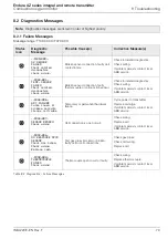
Page 80: ...on 1 NAMUR status Icon see 3 Failure Out of Specification Maintenance Check Function 4 Diagnostic Priority Failure 070 to 100 Out of Specification 048 to 068 Maintenance 022 to 042 Check Function 002 to 020 2 Group Name Electronics Process Configuration Operation 5 Diagnostic Number Internal Use Only Minimum 000 Maximum 047 3 NAMUR Classification Code C Check Function F Failure M Maintenance S Out...

Page 81: ...couple or cold junction sensor Check for related diagnostics Check wiring If problem persists contact local ABB service F096 006 ADC FAILURE Cycle power If problem persists change cartridge Temporary or permanent hardware failure Cycle power to transmitter Replace cartridge If problem persists contact local ABB service F094 007 SENSOR BROKEN Check wiring Cell connection is open circuit Check wirin...

Page 82: ...eplace fuse If problem persists replace heater Faulty heater or temporary surge Replace fuse see Section 4 8 1 page 22 remote transmitter or 4 11 1 page 25 integral transmitter Replace heater in probe If problem persists contact local ABB service F080 013 HEATER TRIPPED Wait for cell temperature to cool down Maximum cell temperature exceeded Wait for temperature to cool down If problem persists co...

Page 83: ...mory or permanent corruption of data Switch power to transmitter off and then on again Check and re enter configuration parameters Replace cartridge If problem persists contact local ABB service F072 002 O2 SENSOR OUT OF LIMITS Address process issue check wiring Process oxygen concentration beyond sensor range Address process issue Check wiring If problem persists contact local ABB service F070 00...

Page 84: ...lty Replace cell Cell is faulty Replace cell S062 033 CAL OFFSET FAILED Cell is faulty Replace cell Cell is faulty Replace cell S060 028 CALIBRATION STABILITY FAILED Check test gas connections Re calibrate Cell input measurement is too noisy Check gas connections Repeat calibration If problem persists contact local ABB service S058 019 MISSED SCHEDULED AUTOCAL Check reason for missed cal Re calibr...

Page 85: ... above 690 C 1274 F but not stable Wait for cell temperature to stabilize 5 minutes S050 004 O2 SENSOR OUT OF RANGE Address process issue or extend operating range Process oxygen concentration beyond set operating range Address process issue or extend oxygen operating range S048 005 TEMP SENSOR OUT OF RANGE Check operating conditions Maximum temperature range for thermocouple exceeded Check operat...

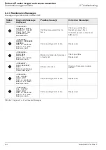
Page 86: ...40 035 SENSOR IMPEDANCE WARNING Cell is reaching end of its life Replace cell Cell is reaching end of its life Replace cell M038 034 SLOW CELL RESPONSE Check gas pipes Replace cell Blocked or broken test gas pipes or faulty cell Check gas pipes Replace cell M036 037 SLOW RECOVERY RATE Diffuser blocked Clean diffuser Diffuser is blocked Clean or if necessary replace diffuser M034 031 CAL OFFSET NEA...

Page 87: ...SENSOR CAL REQUIRED Re calibrate Accuracy check indicates re calibration is required Perform calibration M024 017 SENSOR CAL OVERDUE Re calibrate Customer entered calibration interval exceeded Perform calibration M022 020 MISSED SCHEDULED ACCURACY CHECK Check reason for missed check Re calibrate Device not in operating mode when accuracy check was scheduled Check reason why accuracy check was not ...

Page 88: ...RY TEST MODE Set to run mode before using in the field Transmitter in special factory test mode Set to normal run mode before using in the field C018 043 DEMONSTRATION MODE Set to run mode before using in the field Transmitter in demonstration mode Set to normal run mode before using in the field C016 045 CURRENT OUTPUT 1 IN TEST MODE Output under manual control No action req d Current Output 1 un...

Page 89: ...GAS 2 CALIBRATION Cal in progress No action req d Calibration in progress No action required C006 026 TEST GAS 1 ACCURACY CHECK Cal in progress No action req d Calibration in progress No action required C004 027 TEST GAS 2 ACCURACY CHECK Cal in progress No action req d Calibration in progress No action required C002 042 CONFIGURATION MODE Device is being configured No action req d Calibration in p...

Page 90: ...check or if a new probe cell has been fitted Icon types are shown in Table 8 6 below Fig 8 2 Typical Performance Log and Performance Code Structure Item Icon 1 Calibration check successful Calibration check failed Accuracy check successful Accuracy check failed New probe cell Table 8 6 Performance Log Icons Item Description Item Description 2 hh mm ss YYYY MM DD Time and date of entry 5 RR Recover...

Page 91: ...calculated calibration offset value displayed as a mV value Calibration Factor The calculated calibration factor value Deviation Calibration The difference between the oxygen value as it is being calculated with the newly updated coefficients and the oxygen value as it would have been calculated with the coefficients used before the calibration was performed Accuracy Check The difference between t...

Page 92: ...ation accuracy check is performed either of the test valves are set to manual mode before the test is complete a subsequent calibration or accuracy check is started before the test is complete the difference between the test gas value and process value is less than 10 of the oxygen range the maximum rate of recovery is not achieved within 3 minutes of removal of the test gas New probe cell Not app...

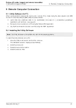
Page 93: ...be downloaded and saved to a compatible spreadsheet application such as Excel see page 93 the device to be operated via a PC using the Remote HMI application any HART command to be read or written using the HART application 9 2 Installing the Utility Software To install the Utility Software onto a PC 1 Insert the Utility Software CD into the PC s CD drive The installation screen is displayed autom...

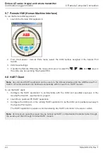
Page 94: ...Service Port switch 1 Ensure the IrDA adaptor is connected see Section 9 3 above 2 Launch the Service Port Switch utility 3 From the drop down list select the COM port A to be used 4 From the drop down list select the client application B to be used Cyclic O P see Section 9 5 page 93 Parameter Dump see Section 9 6 page 93 HMI see Section 9 7 page 94 HART see Section 9 8 page 94 5 Click Connect C T...

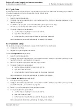
Page 95: ... information to be downloaded Configuration settings Diagnostic Log and Signals View values To run a Configuration settings dump 1 Launch a terminal application 2 Configure the terminal application to communicate with the COM port specified previously in the Service Port Switch see Section 9 4 page 92 3 Press C on the PC keyboard to start the output routine 4 To output the data to a spreadsheet a ...

Page 96: ...nfigure the HART application to communicate with the COM port specified previously in the Service Port Switch see Section 9 page 91 2 Launch any preferred PC HART application 3 Configure the COM port on the running HART application to be the COM port specified previously in the Service Port Switch The HART application operates as normal allowing any HART command to be read or written Note Any stan...

Page 97: ... No Description IM AZ20M EN Maintenance Guide Download the guide from www ABB com analytical instruments AZ20 DTM Software Device Type Manager please contact ABB for details Part No Description AZ200 750 AZ200 751 AZ200 752 AZ20 Transmitter Cartridge Standard Standard Analog O P Standard Digital O P AZ200 758 Type 4 Remote Transmitter Backplane AZ200 757 Type 3 Integral Transmitter Backplane Being...

Page 98: ...ating temperature Storage temperature 40 to 85 C 40 to 185 F Operating humidity Up to 95 RH non condensing Sunlight Store and operate out of direct sunlight Ingress protection Power Supply AC power supply 100 to 240 V AC 10 90 V min to 264 V max 50 60 Hz Electronics 10 W Probe heater 100 W EMC Emissions and immunity Conforms to EN61326 1 2006 Safety General safety Conforms to EN61010 1 2001 Approv...

Page 99: ...y closed 5 A 230 V AC or 30 V DC non inductive Functions User configurable can be activated by one or more of the following signals Process alarm 1 2 3 4 Calibration in progress Calibration failed Out of test gas 1 2 Test gas 1 valve control Test gas 2 valve control Failure diagnostic Out of specification diagnostic Maintenance required diagnostic Function check diagnostic For driving internal aut...

Page 100: ...d diagnostic Function check diagnostic Hart communications Version 5 7 as standard Integration Device Type Manager DTM and Electronic Device Description EDD Provide online offline device configuration online monitoring of measurement values and diagnostic states DTM FDT v1 2 1 compliant Works with FDT framework packages for example ABB Asset Vision Basic EDD Compliant with suitable framework tools...

Page 101: ...to Section 5 4 6 page 53 Refer to Section 5 4 7 page 54 Refer to Section 5 4 8 page 61 Refer to Section 5 4 9 page 63 To first available menu Key 4 Not displayed at Read Only level 5 Displayed only if an option board is fitted 6 The probe type used with the transmitter 7 The transmitter option card fitted ...

Page 102: ...anges or modify the contents of this document without prior notice With regard to purchase orders the agreed particulars shall prevail ABB does not accept any responsibility whatsoever for potential errors or possible lack of information in this document We reserve all rights in this document and in the subject matter and illustrations contained therein Any reproduction disclosure to third parties...

Reviews: