


Technical data
89
3ADW000194R0611 DCS800 Hardware Manual f us
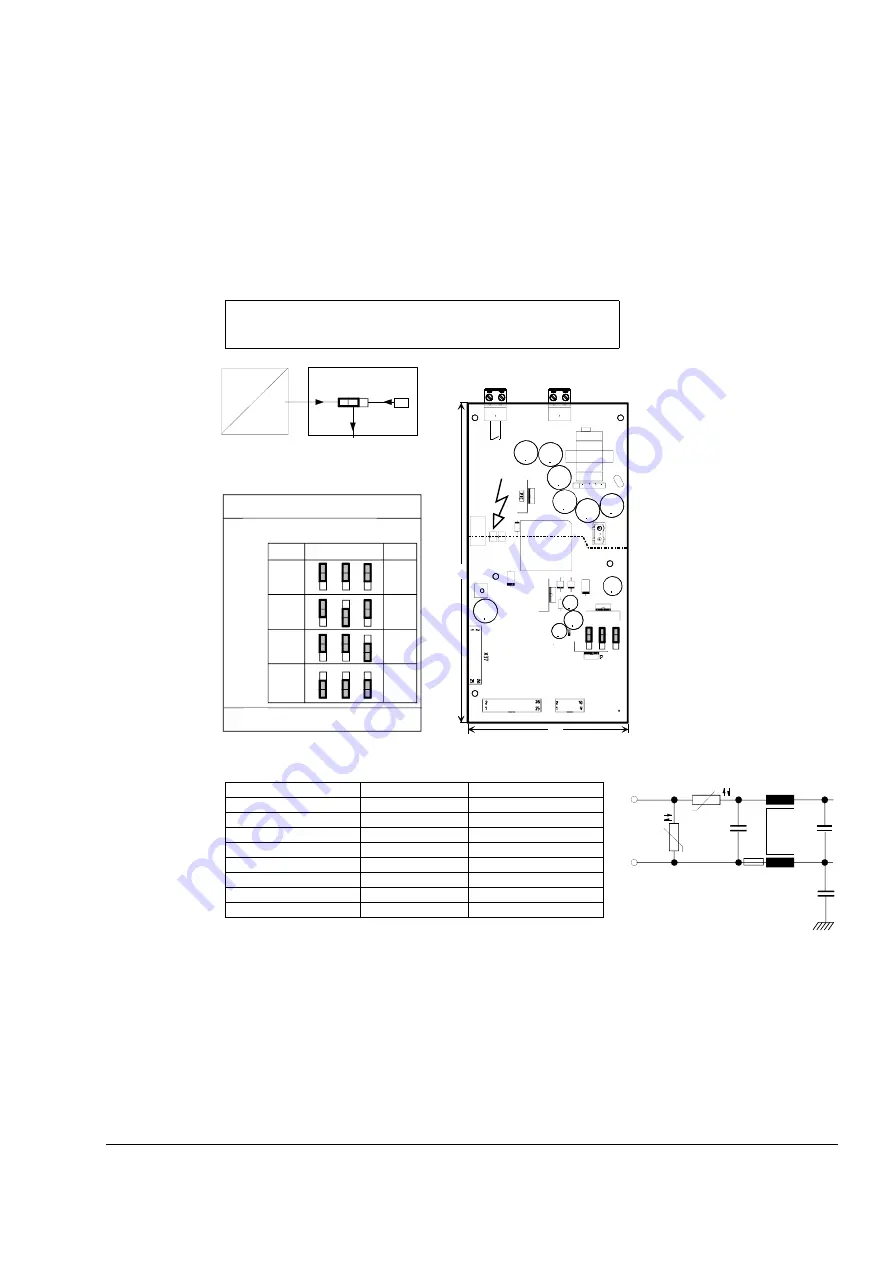
Power Supply Board SDCS-POW-4
The SDCS-POW-4 board is designed for DCS800 converter modules and is mounted on the electronic
support. This board is used for all types of modules type D5, D6 and D7 (>1000 A and rebuild system
DCS800-R).
The SDCS-POW-4 works on a switched mode basis in fly back configuration. It generates all necessary
DC voltages for the SDCS-CON-4 and all other electronic boards. The input voltage is automatically
detected and set to either 230 V AC or to 115 V AC. The following figure shows the instructions for the
selection of the encoder supply voltage.
Auxiliary supply voltage
X99
* Frequently switching ON and OFF increases inrush current
If SDCS-CON-4 input X5: is used for encoder speed measurement, the
incremental encoder supply voltage for 5V, 12 V or 15 V must be selected
by jumpers S3, S4 and S5.
Supply voltage
115 V AC
230 V AC
Tolerance -15%/+10%
-15%/+10%
Frequency
45 Hz ... 65 Hz
45 Hz ... 65 Hz
Power consumption
120 VA
120 VA
Power loss
≤
60 W
≤
60 W
Inrush current *
20 A / 20 ms
10 A / 20 ms
recommended fusing
6 AT
6 AT
Mains buffering
min 30 ms
min 300 ms
Powerfail
95 V
95 V
Output X96-DO8
Potential isolated by relay (NO contact)
MOV- element (275 V)
Contact rating:
AC
:
≤
250 V~/
≤
3 A~
DC
:
≤
24 V-/
≤
3 A
or
≤
115/230 V-/
≤
0.3 A-
Backup supply X95
These two terminals are used to add addi-
tional capacitance to the existing ones to
increase the mains buffering time. More
detailed data is available on request via your
ABB representative.
X37 and X137 are connected in
parallel
X14 is used for SDCS-PAR-1 hard
parallel converters
S
D
C
S
-P
O
W
-4
X96
X99
X95
X3
7
5 V
15 V
24 V
220
110
X3
X4
X5
*
*
X3 X4 X5
12 V
Pow4a.dsf
B
B
A
A
15V
24V
+
-
1
2
N L
DO8
X137
X14
10 11 12
S4
SDCS-CON-4
24V
X5:10
SDCS-POW-4
BA
BA
15
24
X5
X4
X3
5V
12V
15V
24V
B
B
A
A
15V
24V
B
B
A
A
15V
24V
B
B
A
A
15V
24V
AC supply
Encoder supply selection
Relay output
Jumper coding
default value
line potential !
Sense-
function
yes
yes
no
no
encoder supply
The 24 V encoder supply can be selected either directly from
CON-4 board (S4=11-12) or from POW-4 board (S4=10-11);
S4 is located on the CON-4 board
X99:
POW4_in-output_circuit.dsf
3.15 AT
F1
NTC
ϑ
U
Input circuit POW-4
Summary of Contents for DCS800
Page 1: ...DCS800 Hardware Manual DCS800 Drives 20 to 5200 A ...
Page 4: ...3ADW000194R0611 DCS800 Hardware Manual f us ...
Page 20: ...The DCS800 20 3ADW000194R0611 DCS800 Hardware Manual f us ...
Page 54: ...Planning the electrical installation 54 3ADW000194R0611 DCS800 Hardware Manual f us ...
Page 66: ...Installation checklist 66 3ADW000194R0611 DCS800 Hardware Manual f us ...
Page 104: ...Technical data 104 3ADW000194R0611 DCS800 Hardware Manual f us ...


