


53
0
FLt.1
7.07
1000
En1.H
7.04
0
EnI.L
UP
b.Sd1
7.05
7.06
… 4.3
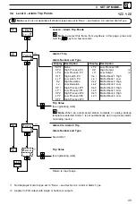
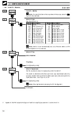
Level 7 – Analog Inputs
Engineering High (I/P1)
[–999 to 9999]
Note. This parameter defaults to the maximum allowed value when
THC or RTD inputs are selected – see Table 4.1.
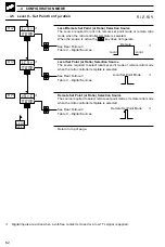
Table 4.1 Engineering Limits, THC & RTD Inputs
Engineering Low (I/P1)
[–999 to 9999]
Note. This parameter defaults to the minimum allowed value when
THC or RTD inputs are selected – see Table 4.1.
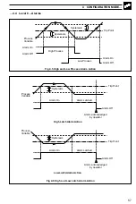
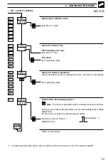
Broken Sensor Drive (I/P1)
NONE
– No action. Actual input values remain valid.
UP
– Input driven to the maximum upscale value (999)
dN
– Input driven to the minimum downscale value (–999)
In the event of a fault being detected on the input, the input is driven in the
direction selected.
Input Filter Time Constant (I/P1)
The input values are averaged over the time set.
[0 to 60 seconds]
Continued…
4
CONFIGURATION MODE…
THC/RTD Type
°
C
°
F
Min.
Max.
Min. Span
Min.
Max.
Min. Span
Type B
–18
1800
710
0
3272
1278
Type E
–100
900
45
–148
1652
81
Type J
–100
900
50
–148
1652
90
Type K
–100
1300
65
–148
2372
117
Type L
–100
900
50
–148
1652
90
Type N
–200
1300
90
–328
2372
162
Type R & S
–18
1700
320
0
3092
576
Type T
–250
300
60
–418
572
108
Pt100
–200
600
25
–328
1112
45
7.04...7.07


