


GETTING STARTED
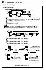
Fig. GS.1 Setting the Parameters
Note. With the
above configuration,
no alarms or limits
have been set and
advanced functionality
(gain scheduling, set
point sources etc.) has
not been enabled.
Step 3 – Setting the Parameters (Fig. GS.1)
A
Power-up the instrument. Press the
and
keys simultaneously and hold for
3 seconds to advance directly to Level 6 – Basic Configuration.
B
Set the appropriate application template, output type and control action. Use the
key to advance between frames and upper
and
keys to adjust the
default values – see Section 4.2 for further information.
Note. When the output type has been selected, the available inputs and outputs
default to the settings shown in Table B on the rear fold-out.
C
If you are not using 4 to 20mA inputs, then select Level 7 using the upper
and
keys and set up Analog Inputs I/P1 to I/P3 to suit your process – see Section 4.3.
D
Controller templates only:
Select Level 2 using the upper
and
keys and set the tune parameters:
• Analog or Motorized Valve Control – set the Proportional, Integral and
Derivative terms.
• Time Proportioning Control – set the Cycle Time, Hysteresis and P, I & D Terms
• Heat/Cool Outputs – set the points at which the Output 1 and Output 2
become active.
E
Press
to return to the Operating displays.
F
Adjust the set point to the required value.
Your COMMANDER 500 is now in operation
APPL
LEV.6
INPt
LEV.7
tUNE
LEV2
B
C
D
+
A
01.SL
t.APP
ANLG
O.tYP
rEV
C.ACt
50
FrEJ
E
50.1
50.5
50
50.1
50.5
50
F
50.1
50.5
50


