


96
…APPENDIX A – CONTROL TEMPLATES
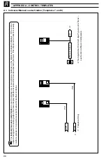
The
Auto/manual Station
provides a backup for a Master controller. In normal operation the COMMANDER 500’s current output follows the master
controller’s output value. A fault in the master system can be identified either by detecting a low signal on the master output
(template 3) or via a digital
signal (template 4). When a fault is detected the COMMANDER 500 selects manual mode with its output either set to the last vali
d master output value
or to a configured output value – see Section 4.6/ Control Configuration/ Configured Output 1. When the master signal is restor
ed or the digital input
returns to its normal state the COMMANDER 500 switches back to auto mode (i.e. COMMANDER 500 output = master output).
The auto/manual station can be used in series or in parallel with the master output signal – see Fig. A1. Parallel operation is
achieved by using
relay 1 in the COMMANDER 500 to energize an external relay (with suitable changeover contacts for switching low level signals)
which selects the output
to be routed to the actuator.
Process V
a
riable
di.1
Auto/Manual
Select
Master Output
ao1
•1
•2
Digital Select
Manual Output
I/P2
Low Signal Select
(Alarm A1)
I/P1
OP1
•2
T
e
mplate 4 only
•1
T
emplate 3 only
.
Alarm
A1 trip value can be set to give the desired low signal detection
…A2.2
Auto/Manual Station (Templates 3 and 4)


