


21
2
OPERATOR LEVEL…
2.7
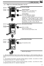
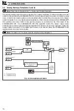
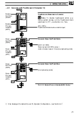
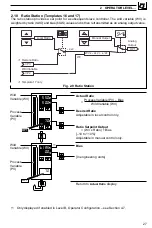
Cascade Control (Templates 11 and 12)
For cascade control, two internally-linked PID controllers are used, with the first (master) PID
controller providing the set point for the second (slave) controller. The master output is weighted
using the cascade ratio (C.rtO) and bias (C.bIA) values to create the slave set point value.
Fig. 2.6 Cascade Controller
Master Process Variable (MPV)
Master Control Set Point (MSPt)
['SPLO' to 'SPHI' – see Section 4.5]
Adjustable in local control only.
Slave Control Output
[0 to 100%] (–10 to 110% for analog outputs)
Adjustable in manual mode only.
Note. With template 12 the
L
L
R
key can be used
to change between local/remote set point values.
Slave Process Variable (SPV)
Slave Set Point (SSPt)
['SPLO' to 'SPHI' – see Section 4.5]
Adjustable in manual or local slave set point modes
only.
Note. The
L
L
R
key can be used in this frame to
change between cascade and local slave set points.
Continued…
•1
With the Ramping Set Point function enabled (see Section 3.3, Set Points/ Ramp Rate), the
bargraph shows the actual (ramping) set point value and the digital display shows the target set
point value.
RSPt
MPV
I/P3
I/P1
I/P2
OP1
Local
Set Point
Remote Set Point
input
Master PV Input
Slave PV Input
Slave Set
Point
Slave PID
Control Loop
SPV
Master
PID
Control Loop
•1
•1 Template 12 Only
LSPt
SSPt
L
L
R
Manual Output
RSPt x
rAtO
+
bIAS
M.OP x
CrtO
+
CbIA
L
L
R
SSPt
M.OP
450.2
500.0
Master
Set Point
(MSPt)
Master
Process
Variable
(MPV)
70
OP1
450.2
500.0
SLV
70
OP1
MST
Slave
Set Point
(SSPt)
Slave
Process
Variable
(SPV)
•1
•1


