
9
C1 3 0 0/A DVA NCE D CI RCU L A R CH A RT R ECOR DE R
| C I/C 1 3 0 0 - EN R E V. C
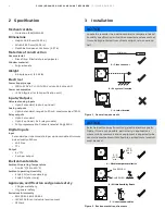
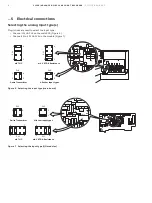
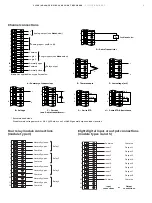
Channel connections
Four relay module connections
(module type 3)
Eight digital input or output connections
(module types 4 and 5)
Analog output (see
Note below)
+
–
+
+
–
–
+
+
–
–
+
–
+
–
Logic inputs (see
Note below)
Relay output
A – Summary of connections
B – Voltage
C – Current
(non 2-wire transmitters)*
G – 3-wire RTD
H – 2-wire RTD & Resistance
F – Low voltage (mV)
E – Thermocouple
D – 2-wire Transmitter
Note. Not applicable on type 2 modules.
* Recommended diode:
Diode forward voltage must be > 0.8 V @ 20 mA or use 2 x 1N4001 general purpose diodes in series.
See
Note below
Link
White
White
Red
Red
Red
Tx
Analog input – see
B to H)
Common
Common
Normally open
1
2
3
4
5
6
3
6
3
6
3
6
3
4
4
4
5
5
6
6
4
6
7
8
9
10
11
12
Logic 2
Normally closed
Logic 1
Relay 1
Normally closed
Normally open
Common
Normally closed
Normally open
Common
Normally closed
Normally open
Common
Normally closed
Normally open
Common
1
2
3
4
5
6
7
8
9
10
11
12
Relay 2
Relay 3
Relay 4
Common
Common
Input 1
1
2
3
4
5
6
7
8
9
10
11
12
Input 2
Input 3
Input 4
Input 5
Input 6
Input 7
Input 8
Common
Common
Output
connections
Input
connections
or
Output 1
Output 2
Output 3
Output 4
Output 5
Output 6
Output 7
Output 8


