
C1 3 0 0/A DVA NCE D CI RCU L A R CH A RT R ECOR DE R
| C I/C 1 3 0 0 - EN R E V. C
11
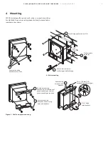
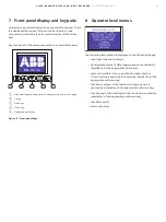
7 Front panel display and key pads
Operation is performed using the keys on the front panel. There
is a dedicated front panel for each control loop, but main
programming of device is performed using the left hand key
pad.
Key functions for the membrane switch are described below:
A
Side scroll key, allows operator to advance to the next menu page
B
Up key
C
Down key
D
Menu key
E
Dedicated pen lift key
Figure 8 Front panel keys
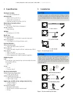
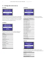
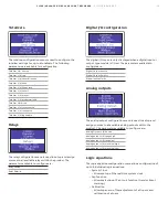
8 Operator level menus
The following information is displayed in the Operating Pages:
• Input (pen) channel readings
• Data logging status (if data logging option is enabled by
installation of the appropriate hardware)
• System time/date (if any one of the Totalizer, Math or
Timers software options are enabled by installation of the
appropriate software key)
• Totalizer readings (if the totalizer software option is
enabled by installation of the appropriate software key)
• Totalizer log (if the totalizer software option is enabled by
installation of the appropriate software key)
• Totalizer control
• Alarm set points


