
C
I/
C
13
0
0
-E
N R
E
V. C
10
.2
0
20
—
ABB Limited
Measurement & Analytics
Howard Road, St. Neots
Cambridgeshire, PE19 8EU
UK
Tel: +44 (0)870 600 6122
Fax: +44 (0)1480 213 339
Mail: [email protected]
—
We reserve the right to make technical changes or modify the contents of
this document without prior notice. With regard to purchase orders, the
agreed particulars shall prevail. ABB AG does not accept any responsibility
whatsoever for potential errors or possible lack of information in this
document.
We reserve all rights in this document and in the subject matter and
illustrations contained therein. Any reproduction, disclosure to third
parties or utilization of its contents – in whole or in parts – is forbidden
without prior written consent of ABB.
© ABB 2020
ABB Inc.
Measurement & Analytics
125 E. County Line Road
Warminster
PA 18974
USA
Tel: +1 215 674 6000
Fax: +1 215 674 7183
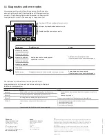
11 Diagnostics and error codes
Upon power up the unit will perform a series of self checks to
ensure that the unit and fitted modules are fitted and working
correctly. The following figure describes what is shown on the
front panel of the unit in the event any of these tests fail:
The instrument is also able to provide you with a pre-
programmed error in the event of a failure relating to the input
itself in normal operation:
Message
Reason
Action
Error1
Unspecified error from the Analog to Digital Converter
• Check that the input/output board is located correctly in its
socket
• Power down and up
If the error message is still present, contact the ABB Ltd
Error2
Corrupt data from the Analog to Digital Converter
Error3
No reply from the Analog to Digital Converter
F-inpt
Input is above or below fault detection level
OR
Input exceeds the limits for the linearizer selected
Check input source for possible broken sensor
Check input connections
Check input link position
Check input configuration
Component
Possible cause
Action
Main board CPU and configuration test results
Module identification and test results
Module in position 2
Module in position 3
Module in position 4
Analog input and/or analog output
calibration is corrupt
Configuration stored in non-volatile memory is corrupt.
Check and correct program data.
If the fault persists, contact the company.
Power down and then up again.
If the fault persists, contact the company.
Module in position 5
Module in position 6
Main board
Software key
Software key identification and test result
Main: CFG Test :Pass
SKey:Type B :Pass
Mod2:Not Fitted
Mod3:Not Fitted
Mod4:Not Fitted
Mod5:Not Fitted :Pass
Mod6:Not Fitted :Pass


