
6
C1 3 0 0/A DVA NCE D CI RCU L A R CH A RT R ECOR DE R
| C I/C 1 3 0 0 - EN R E V. C
…4 Mounting
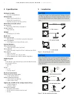
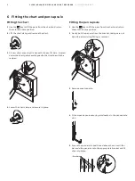
NOTICE
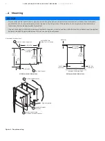
• The recorder can be inserted into a panel cut-out of any size between the minimum and maximum dimensions illustrated,
provided the cut-out is positioned centrally relative to the fixing holes. If the panel cut-out is larger than the maximum, a
locally manufactured adaptor plate is required.
• If panel-mounting to NEMA 4X hosedown standard is required, a continuous bead of suitable silicon sealant must be applied
between the case flange and the panel. Do not use the optional gasket.
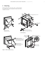
Figure 4 Panel-mounting
Minimum cut-out dimensions
Maximum cut-out dimensions
Secure in panel using
four bolts, nuts and washers
Drill four suitable holes
Dimensions in inches (mm)
Mark four mounting holes
4 holes 0.281 dia.
or tap for ¼ in. thread
14.00 (355.6)
12.72 (323.08)
minimum
0.20 (5.0)
Ensure cut-out positioned centrally
between mounting holes
13.7 (348.0)
maximum
14.6
(371.0)
maximum
12.72
(323.08)
minimum
11.25
(285.8)
14.19
(360.4)
1.70
(43.2)
0.64 (16.25)
0.15 (3.8)
minimum
0.15 (3.8)
minimum
Locate instrument
in cut-out
Optional gasket
Cut hole in panel
4
5
3
2
1


