ABB C1300 Quick Start Manual Download Page 3

C1 3 0 0/A DVA NCE D  CI RCU L A R  CH A RT  R ECOR DE R

  |  C I/C 1 3 0 0 - EN R E V. C

3

Potential safety hazards

Electrical

 WARNING

To ensure safe use when operating this equipment, the 
following points must be observed:
•  Up to 240 V AC may be present. Be sure to isolate the 

supply before removing the terminal cover.

•  Normal safety precautions must be taken to avoid the 

possibility of an accident occurring when operating in 
conditions of high pressure and/or temperature.

Safety advice concerning the use of the equipment 
described in this publication or any relevant Material Safety 
Data Sheets (where applicable) can be obtained from the 
Company, together with servicing and spares information.

Safety standards

This product has been designed to satisfy the requirements of 
IEC61010-1:2010 3rd edition ‘Safety Requirements for Electrical 
Equipment for Measurement, Control and Laboratory Use’ and 
complies with US NEC 500, NIST and OSHA.

EC Directive 89/336/EEC

Electrical – In order to meet the requirements of the EC 
Directive 89/336/EEC for EMC regulations, this product must 
be used in an industrial environment.

End-of-life disposal

  The recorder contains a small lithium battery that 

must be removed and disposed of responsibly in 
accordance with local environmental regulations.

The remainder of the recorder does not contain any 
substance that causes undue harm to the 
environment and must be disposed of in accordance 
with the Directive on Waste Electrical and Electronic 
Equipment (WEEE). It must not be disposed of in 
Municipal Waste Collection.

  ABB is committed to ensuring that the risk of any 

environmental damage or pollution caused by any of 
its products is minimized as far as possible. The 
European Waste Electrical and Electronic Equipment 
(WEEE) Directive that initially came into force on 13 
August 2005 aims to reduce the waste arising from 
electrical and electronic equipment; and improve the 
environmental performance of all those involved in 
the life cycle of electrical and electronic equipment.


In conformity with European local and national 
regulations, electrical equipment marked with the 
above symbol may not be disposed of in European 
public disposal systems after 12

th

 August 2005.

Symbols

One or more of the following symbols may appear on the 
equipment labelling:

Warning – refer to the manual for instructions

Caution – risk of electric shock

Protective earth (ground) terminal

Earth (ground) terminal

Direct current supply only

Alternating current supply only

Both direct and alternating current supply

The equipment is protected through double insulation

Restriction of Hazardous Substances (RoHS)

  The European Union RoHS Directive and subsequent 

regulations introduced in member states and other 
countries limits the use of six hazardous substances 
used in the manufacturing of electrical and electronic 
equipment. Currently, monitoring and control 
instruments do not fall within the scope of the RoHS 
Directive, however ABB has taken the decision to 
adopt the recommendations in the Directive as the 
target for all future product design and component 
purchasing.

Cleaning

The recorder can be hosed down if it has been installed to  
IP66/NEMA 4X standards. Warm water and a mild detergent  
can be used.

Summary of Contents for C1300

Page 1: ...1300 Advanced circular chart recorder Datasheet DS C1300 EN C1300 Advanced circular chart recorder User Guide supplement Advanced software options IM C1300 C1300 Advanced circular chart recorder User...

Page 2: ...1 Diagnostics and error codes 16 1 Health Safety Document symbols Symbols that appear in this document are explained below DANGER The signal word DANGER indicates an imminent danger Failure to observe...

Page 3: ...nicipal Waste Collection ABB is committed to ensuring that the risk of any environmental damage or pollution caused by any of its products is minimized as far as possible The European Waste Electrical...

Page 4: ...V TTL 5 mA per output Environmental data Ambient Operating Temperature 0 to 55 C 32 to 130 F Ambient operating Humidity 5 to 95 non condensing 5 to 80 chart only Approvals certification and general s...

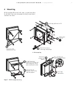
Page 5: ...ipe mounting optional Secure mounting brackets 4 to case Drill suitable holes 4 11 06 281 0 14 81 376 3 Mark fixing centers on wall 4 2 in 60 mm OD horizontal or vertical pipe Secure using two nuts an...

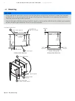
Page 6: ...silicon sealant must be applied between the case flange and the panel Do not use the optional gasket Figure 4 Panel mounting Minimum cut out dimensions Maximum cut out dimensions Secure in panel using...

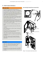
Page 7: ...conforms to installation category II of IEC 61010 All connections to secondary circuits must have basic insulation After installation there must be no access to live parts for example terminals Termin...

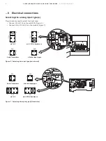
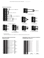
Page 8: ...e main PCB Figure 6 Channels 2 to 4 PL1 PL3 on the module Figure 7 Figure 6 Selecting the input type main board Figure 7 Selecting the input type I O modules mA V RTD Resistance 5 4 8 1 2 3 1 4 2 3 1...

Page 9: ...st be 0 8 V 20 mA or use 2 x 1N4001 general purpose diodes in series See Note below Link White White Red Red Red Tx Analog input see B to H Common Common Normally open 1 2 3 4 5 6 3 6 3 6 3 6 3 4 4 4...

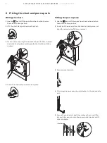
Page 10: ...d aligned to the timeline with the red pen 4 Lower the chart clamp and secure in place Fitting the pen capsule 1 Use the key to lift the pens from the chart and return them to the home position 2 Gent...

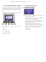
Page 11: ...ated pen lift key Figure 8 Front panel keys 8 Operator level menus The following information is displayed in the Operating Pages Input pen channel readings Data logging status if data logging option i...

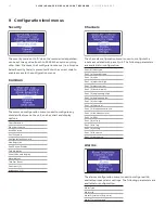
Page 12: ...play Other Channels display Alarm Adjust Totalizer Reset Contrast 1 2 Brightness 1 2 Channels The channels configuration menu is used to configure the inputs associated with pens 1 to 4 The following...

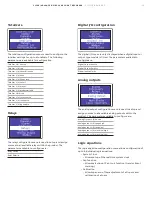
Page 13: ...Digital I O configuration The digital I O menu is only displayed when a digital input or output type module is fitted The parameters available to configure are Digital Output source Digital Output Po...

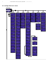
Page 14: ...R CHART RECORDER CI C1300 EN REV C 10 Configuration level menus Security code Section 10 page 14 12 hours or 24 hours selected Anything other than timed Common Channels Alarms Totalizers Relays Digita...

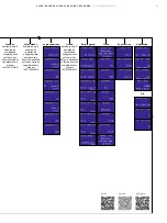
Page 15: ...OD Math blocks Available only if enabled by installation of appropriate software key Refer to Advanced software options supplementary manual IM C1300 ADV Logic equations Timers Available only if enabl...

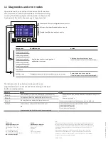
Page 16: ...s also able to provide you with a pre programmed error in the event of a failure relating to the input itself in normal operation Message Reason Action Error1 Unspecified error from the Analog to Digi...

Reviews: