


1473-1-8162
│
Rev. 01
│
17.12.2012
Operating Instructions
Busch-Jalousiecontrol
®
II
Pos: 2 /#N eustruktur #/Online-Dokumentation (+KN X)/Titelbl ätter/Ti mer/Titelbl att 6411 Jal ousiecontrol II-Ei nsatz @ 30\mod_1348658450813_15.docx @ 239241 @ @ 1
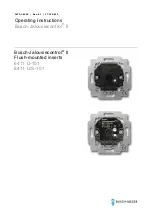
Busch-Jalousiecontrol
®
II
Flush-mounted inserts
6411 U-101
6411 U/S-101
=== Ende der Liste für T extmar ke Cover ===