■
Continuous motor cable shield/conduit or enclosure for equipment
on the motor cable
To minimize the emission level when safety switches, contactors, connection boxes or
similar equipment are installed on the motor cable between the drive and the motor:
•
Install the equipment in a metal enclosure.
•
Use either a symmetrical shielded cable, or install the cabling in a metal conduit.
•
Make sure that there is a good and continuous galvanic connection in the shield/conduit
between drive and motor.
•
Connect the shield/conduit to the protective ground terminal of the drive and the motor.
■
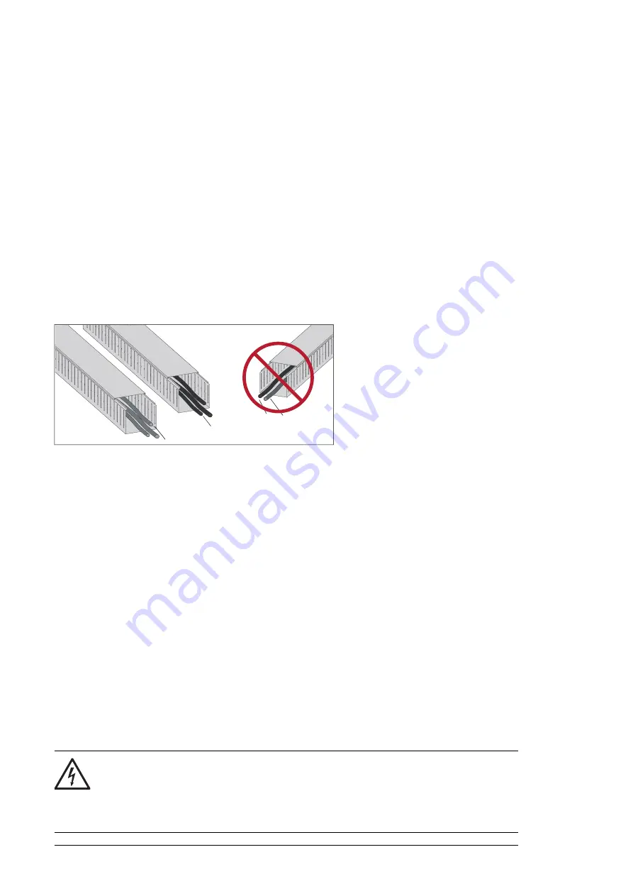
Separate control cable ducts
Put 24 V DC and 230 V AC (120 V AC) control cables in separate ducts, unless the 24 V DC
cable is insulated for 230 V AC (120 V AC) or insulated with an insulation sleeving for
230 V AC (120 V AC).
24 V DC
230 V AC
(120 V AC)
230 V AC
(120 V AC)
24 V DC
Implementing short-circuit and thermal overload protection
■
Protecting the input cabling and the drive upon a short-circuit
To protect the input cabling in short-circuit situations, install fuses or a suitable circuit breaker
at the supply side of the cabling.
The drive is equipped with internal AC fuses as standard. In case of a short-circuit inside
the drive, the AC fuses protect the drive, restrict drive damage, and prevent damage to
adjoining equipment.
■
Protecting the motor and motor cable in short-circuits
The drive protects the motor cable and motor in a short-circuit situation when the motor
cable is sized according to the nominal current of the drive. No additional protection devices
are needed.
■
Protecting the drive and the power cables against thermal overload
The drive protects itself and the input and motor cables against thermal overload when the
cables are sized according to the nominal current of the drive. No additional thermal protection
devices are needed.
WARNING!
If the drive is connected to multiple motors, use a separate circuit breaker or fuses
for protecting each motor cable and motor against overload. The drive overload
protection is tuned for the total motor load. It may not trip due to an overload in
one motor circuit only.
76 Guidelines for planning the electrical installation
Summary of Contents for ACS880-07LC
Page 1: ... ABB INDUSTRIAL DRIVES ACS880 07LC drives Hardware manual ...
Page 2: ......
Page 4: ......
Page 12: ...16 Resistor braking Further information 12 Table of contents ...
Page 22: ...22 ...
Page 63: ...Mechanical installation 63 10 ...
Page 64: ...64 ...
Page 91: ...a b c 4 a 8 b 16 18 PE PE 10 13 12 Electrical installation 91 11 ...
Page 100: ...With FDPI 02 modules OPEN TERMIN ATED 1 1 2 2 OPEN TERMINATED 3 100 Electrical installation ...
Page 104: ...104 ...
Page 118: ...118 ...
Page 124: ...124 ...
Page 138: ...8 9 138 Maintenance ...
Page 139: ...11 12 12 6 10 Maintenance 139 ...
Page 150: ...150 ...
Page 160: ...160 ...
Page 183: ...Technical data 183 ...
Page 184: ...184 Technical data ...
Page 189: ... Dimension drawing examples ACS880 07LC 0850A 7 Dimensions 189 ...
Page 190: ...ACS880 07LC 1660A 7 6 pulse 190 Dimensions ...
Page 191: ...ACS880 07LC 1660A 7 A004 12 pulse Dimensions 191 ...
Page 192: ...ACS880 07LC 3260A 7 192 Dimensions ...
Page 195: ... 600 mm with main breaker double busbar bottom cable entry Dimensions 195 ...
Page 197: ...Inverter module cubicle with two R8i modules bottom cable exit Dimensions 197 ...
Page 198: ...Inverter module cubicle with three R8i modules bottom cable exit 198 Dimensions ...
Page 199: ...Brake chopper cubicle Dimensions 199 ...
Page 200: ...200 ...
Page 216: ... Declaration of conformity 216 The Safe torque off function ...
Page 217: ...The Safe torque off function 217 ...
Page 218: ...218 ...
Page 220: ...220 ...


