P. 21 - Chap. 2 Symbols
2
Symbols
G
B
2.1
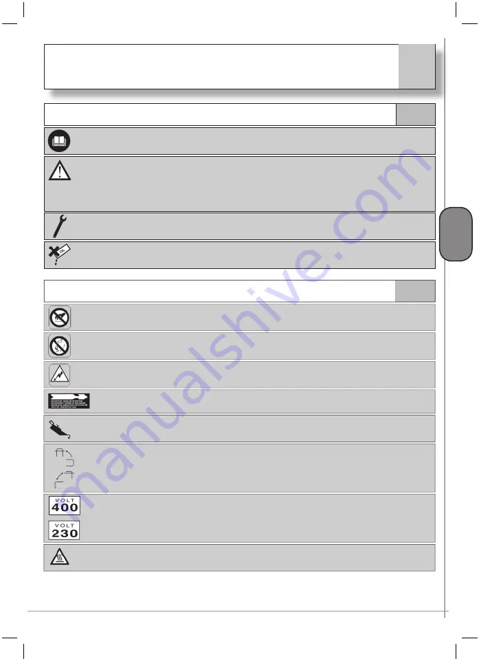
Symbols in the manual
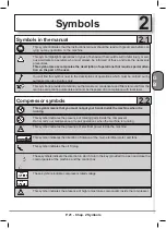
This symbol indicates that the instructions manual should be read with great care before car-
rying out any operation on the machine
This symbol highlights operations or types of behaviour that could result in fatal injury or seri-
ous accidents to operators who must always be informed of these and take the necessary
precautions.
This symbol also accompanies the description of operations that require special atten-
tion on the part of the user.
You will fi nd this symbol next to the descriptions of operations which must be carried out by
authorized service Centres only
This symbol is provided to remind you that waste oil, condensate and fi lters removed from the
machine are polluting materials and must be disposed of in compliance with local laws
2.2
Compressor symbols
This symbol means that you must not put your hands inside the machine when it is
running
This symbol indicates the presence of rotating parts inside the compressor
Do not carry out maintenance or repair operations when the machine is running
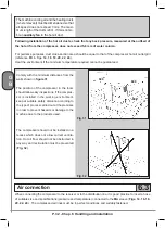
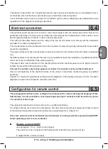
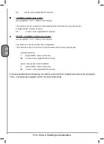
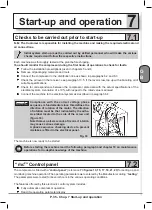
This symbol indicates the presence of electrical power inside the machine
This symbol indicates the direction of rotation of the main electrical motor and fans
This symbol indicates the oil fi ll plug
These symbols indicate the direction in which to turn the key (provided) to open and close the
control panels of the machine and the control box
These symbols indicate compressor rated voltage
This symbol indicates the presence of high temperature components inside the compressor
Summary of Contents for FORMULA Series
Page 1: ...GENESIS FORMULA MODULO 5 5 15 kW USE AND MAINTENANCE HANDBOOK GB ...
Page 2: ......
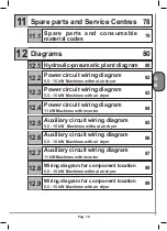
Page 82: ...P 80 Chap 12 Diagrams G B 12 Diagrams Hydraulic pneumatic plant diagram 12 1 ...
Page 85: ...P 83 Chap 12 Diagrams G B Power circuit wiring diagram 5 5 15 kW Machines with air dryer 12 3 ...
Page 86: ...P 84 Chap 12 Diagrams G B Power circuit wiring diagram 11 kW Machines with inverter 12 4 ...
Page 89: ...P 87 Chap 12 Diagrams G B Auxiliary circuit wiring diagram 11 kW Machines with inverter 12 7 ...


