Chapter 6
Programming
6-19
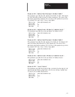
Parameter 183 – Velocity Damping Selection (Vel Damp Selct)
This parameter is associated with the auto tune function and specifies the
velocity damping desired by the user. The auto tuning procedure calculates
a new set of Velocity Loop Gains (parameters 168 & 169) and a new
Current Rate Limit (parameter 158) when the user initiates the Auto Tune
Calculate function. Refer to Figure 8.1 for further information.
Parameter Type:
View/modify in Modify level and Maintenance level
Minimum Value:
0
Maximum Value:
3
Default Value:
0
0
zeta = 0.87
1
zeta = 1.0
2
zeta = 0.7
3
zeta = 1.4
Parameter 184 – Velocity Low Pass Filter Band-
width (Vel Low Pas BW)
Specifies the single pole low pass velocity feedback filter bandwidth. A
value of 30000 disables the filter.
Parameter Type:
View/modify in Modify level and Maintenance level
Minimum Value:
0 rads/second
Maximum Value:
30000 rads/second
Default Value:
30000 rads/second
Parameter 185 – Lead/Lag Velocity Fdbk. Filter Gain (Lead/Lag Gain)
Specifies the gain of the velocity feedback filter. A value of 1.00 disables
the filter.
Parameter Type:
View/modify in Modify level and Maintenance level
Minimum Value:
–10.00 (lag)
Maximum Value:
+10.00 (lead)
Default Value:
1.00
Parameter 186 – Lead/Lag Velocity Fdbk. Filter BW. (Lead/Lag BW)
Specifies the bandwidth of the velocity feedback filter.
Parameter Type:
View/modify in Modify level and Maintenance level
Minimum Value:
0 rads/second
Maximum Value:
2700 rads/second
Default Value:
250 rads/second
Parameter 187 – Auto Tune Velocity (Auto Tune Vel)
This parameter specifies the maximum velocity attained during an auto
tune cycle.
Parameter Type:
View/modify in Modify level and Maintenance level
Minimum Value:
–2000 rpm
Maximum Value:
+2000 rpm
Default Value:
+1000 rpm
Summary of Contents for 1391-DES Series
Page 2: ...User Manual 1391 DES Digital AC Servo Drive ...
Page 10: ...Chapter 1 Introduction 1 10 End of Chapter ...
Page 38: ...Chapter 5 Inputs Outputs and Switch Settings 5 8 End of Chapter ...
Page 85: ...Chapter 8 Start Up 8 16 End of Chapter ...
Page 89: ...Chapter 9 1326 AC Servomotors 9 4 End of Chapter ...
Page 107: ...Chapter 11 Troubleshooting 11 12 End of Chapter ...
Page 123: ...Appendix B Interconnect Drawings B 12 End of Appendix ...
Page 127: ...Appendix C Cable Information C 4 End of Appendix ...
Page 135: ...Appendix E Parameter Record E 8 End of Appendix ...
Page 136: ...Notes ...
Page 137: ...Notes ...
Page 138: ...Notes ...
Page 139: ...Notes ...
Page 140: ...Notes ...
Page 141: ...Notes ...
Page 142: ...Notes ...
Page 143: ...Notes ...
Page 144: ...Notes ...
Page 145: ...Notes ...
Page 148: ...IMC is a trademark of Allen Bradley Company Inc ...


