Standard controller –
Installation manual
AAT SYSTEMY BEZPIECZEŃSTWA Sp. z o.o.
All rights reserved.
9
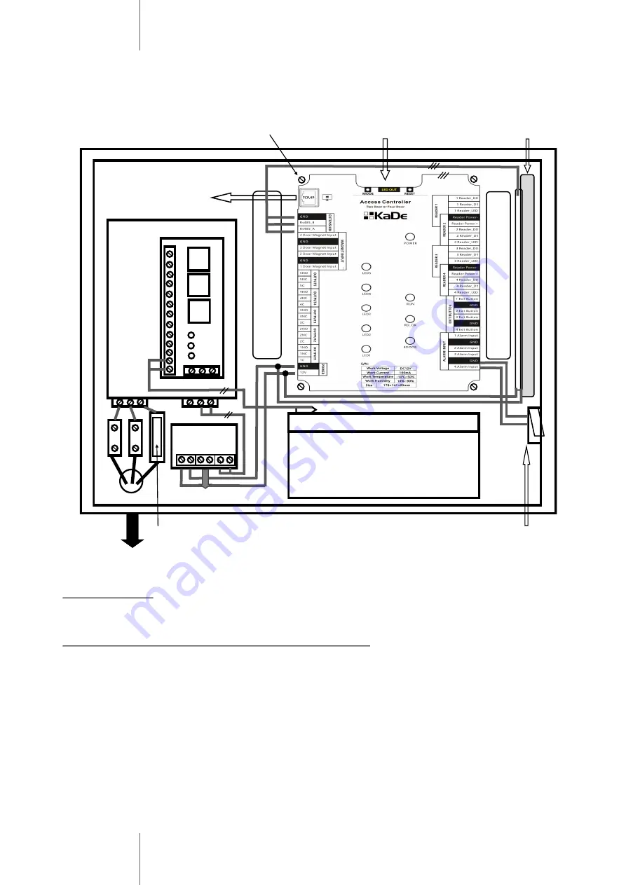
7. APSAAT4 power supply for KDH
-
KS3024
-
IP controller
To Ethernet
Po
w
er
s
u
p
p
ly
12
VDC
5A
Co
n
tr
ol
o
u
tp
u
ts
EPS
PSU
LoB
Battery 7Ah
Mains supply 230VAC
Power
distributor
Locks power supply
KDH
-
MOD2000INOUT module
Controller module
Fuse T3,15A/250V
AUX1+
LoB
PSU
EPS
Power distributor
Provides two independent outputs, protected by polymer fuses:
•
to controller and I/O module AUX1/COM
-
0,9A, 13,8 VDC
•
to locks, sirens AUX2/COM
-
4A, 13,8 VDC
Control outputs
-
relay and transistor with LED indication:
EPS
-
technical output for absence of AC supply
PSU
-
output signalling absence of DC voltage/power supply failure
LoB
-
output signalling low battery voltage
Above mentioned outputs should be connected with free alarm line on controller or on extension
module and monitoring schedule should be enabled.
Diagram above shows only connections, which should be made inside the enclosure, between
power supply module, controller module, I/O module, tamper switch and battery.
Detailed information about all parameters and terminals in APSAAT4 power supply are specified
in the operating manual of the power supply on the website:
http://www.aat.pl/pl/products/2930/APSAAT4
Base hole
Enclosure door tamper switch
Summary of Contents for KaDe KDH-KS3012-IP
Page 12: ......


