Page 74
01/2007
AMT/PTD/PBX/0020/2/4/EN
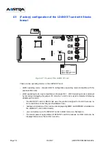
4.4
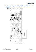
(Factory) configuration of the LD4 RJ card with RJ45
format
Figure 4-4: Overview of the LD4 RJ card
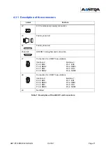
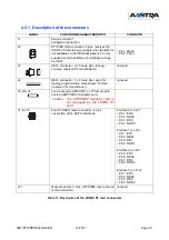
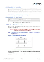
4.4.1 Description of RJ45 connectors
•
8 x 8-pin RJ 45 ports
Figure 4-5: Front panel of LD4 RJ card
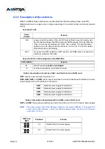
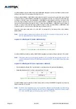
Check that signals match pins:
Table 6: S0 connector pinout on the LD4 RJ card
LINE NO.
Pin No.
S3
S2:
S1
S0
1
2
3
4
5
6
7
8
M40 V
RD3
ED3
NED3
NRD3
P40 V
RD2
ED2
NED2
NRD2
RD1
ED1
NED1
NRD1
RD0
ED0
NED0
NRD0
J1
J5
J2
J4
J6
J1
J2
J7
J8
J4
SW1
SW8
SW7
ADAPT
SW3
SW4
SW5
SW6
J3
CONSOLE
LD4 X
T
0
S
0
T
3
S
3
P
B
X
_
M
A
T
R
IX
_
C
A
R
T
E
_
L
D
4
R
J
_
F
A
V
_
0
1
_
0
1
Summary of Contents for NeXspan C
Page 2: ...Page 2 01 2007 AMT PTD PBX 0020 2 4 EN...
Page 20: ...Page 20 01 2007 AMT PTD PBX 0020 2 4 EN...
Page 66: ...Page 66 01 2007 AMT PTD PBX 0020 2 4 EN...
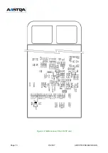
Page 70: ...Page 70 01 2007 AMT PTD PBX 0020 2 4 EN Figure 4 2 Bottom view of the LD4 ST card...
Page 134: ...Page 134 01 2007 AMT PTD PBX 0020 2 4 EN...

