AMT/PTD/PBX/0020/2/4/EN
01/2007
Page 65
3.5
Installing and connecting the base stations
3.5.1 Installing the base stations
•
The base stations must be positioned at the exact point determined by the deployment study.
Moving the position of the base station by 1 or 2 meters may have a detrimental effect on
transmission and reception within the radio area.
•
To avoid deterioration of radio coverage, avoid installing the base stations on metallic
surfaces or on load-bearing walls made of reinforced concrete. If a metallic surface cannot be
avoided, use a 50 to 80 cm extension bracket.
•
Do not place base stations higher than 4 meters from the ground. This is to facilitate access
for maintenance purposes and to ensure correct radio range.
•
Do not install base stations in false ceilings, or in a horizontal position.
•
The minimum distance between co-located base stations must be 30 to 50 cm outside
dimensions: possibility of having 3 co-located base stations per cell.
3.5.2 Connecting base stations
When connecting base stations, several factors affect the quality and reliability of the installation.
PBX and distribution frame
Check the ground connection on the PBX and on the distribution frame(s). A single ground
connection is used.
Wires used
Wiring is carried out using an STP5 cable.
•
If you want to recover existing wiring, all the shield wires must be connected to the distribution
frame, which must be grounded. The shield wire is connected from the wire on the distribution
frame.
•
Wiring with quad wire with shield: this must be grounded.
•
Wiring with quad wire without shield (not recommended)
•
Wiring with category 4 or 5 computer cable: wiring must be identical for category 4 and 5.
However, it is possible to ground the unused pair(s) (pair 7 – 8) (but this is not recommended
for pair 1 – 2).
•
In all cases, you must respect the wire manufacturer’s technical characteristics.
•
If possible, check the link with a scanner.
•
On the NeXspan C/S/L/D range, connection is set up using a category 5 wire or a wire with
twisted pairs (for connection with RJ45 connectors). A twisted cable (a 3/6 pair and a 4/5 pair)
is required to connect DECT base stations to the integrated S0 accesses of the CPU card.
•
Regarding the F1 range, for a wall-mounted or CTM distribution frame, wiring must be done
with the twisted telephone jumper.
For information on wiring base stations according to PBX type, refer to the corresponding section
on “Implementation of hardware”.
Summary of Contents for NeXspan C
Page 2: ...Page 2 01 2007 AMT PTD PBX 0020 2 4 EN...
Page 20: ...Page 20 01 2007 AMT PTD PBX 0020 2 4 EN...
Page 66: ...Page 66 01 2007 AMT PTD PBX 0020 2 4 EN...
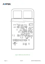
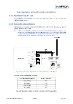
Page 70: ...Page 70 01 2007 AMT PTD PBX 0020 2 4 EN Figure 4 2 Bottom view of the LD4 ST card...
Page 134: ...Page 134 01 2007 AMT PTD PBX 0020 2 4 EN...

