Instruction manual TWI 35-130 G/TWI 45-190 G
39
7.1 Introduction
7.2 Start
up
7.3
Heating cycle of the
device
This chapter will cover in the given order:
•
Start up.
•
Heating cycle of the device.
Start up the device by:
1. Filling the device
(5 “Fill”)
.
2. Opening the gas valve
(3.5 “Connections diagram”)
.
3. Switching on the voltage of the device using the main switch between the
device and the electricity mains.
4. Setting the device to the desired temperature.
This device has been equipped with an electronic hot surface igniter that ignites
the burner. There are three LEDs indicating the different operating conditions.
Green: the device is live.
Yellow: a heat demand has been detected; this indicates the beginning of the
ignition
cycle.
Red:
the gas valve is open.
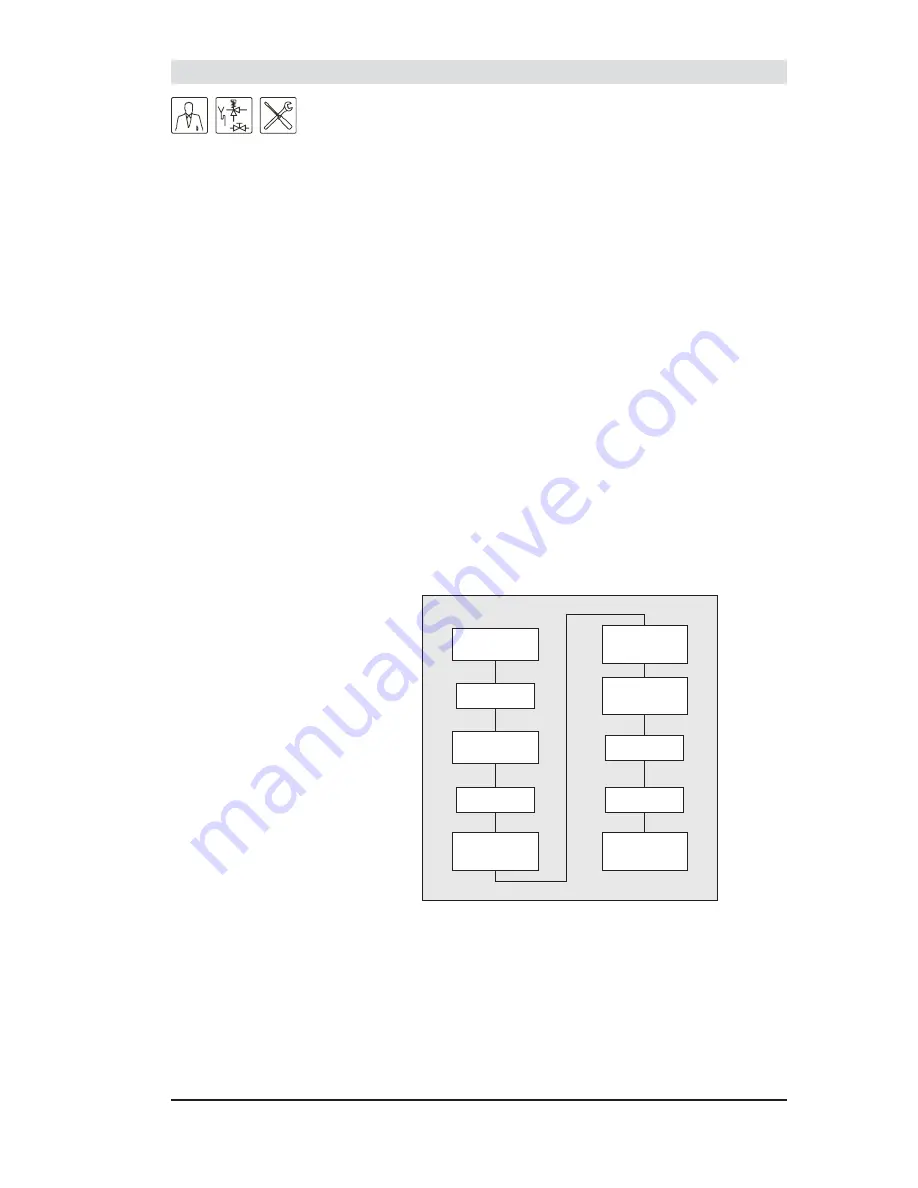
Heating cycle of the device
As soon as there is a heat demand, the fan pre-purges for 6 seconds in order
to remove any combustion gases still present. Then the fan stops and heats the
hot surface igniter for 35 seconds. After this pre-heating period, the fan starts
and the gas valve opens. This blows the air/gas mixture over the heated hot
surface igniter and ignites the burner. The hot surface igniter switches off and
subsequently works as a
fl
ame probe for measuring if the ignition has taken
place. If the hot surface igniter detects loss of the
fl
ame, it will shut off the gas
supply to the burner.
7
Start up
Toestel voorzien
van voedingsspanning
Groene LED
aan
Ongeveer 35 sec.
voorgloeien
Ventilator begint te
draaien, gasklep
open
Warmtevraag
gedetecteerd
Gele LED aan
Rode LED aan
Brander ontsteekt
Ventilator spoelt
ongeveer 6 seconden
voor
Toestel blijft in bedrijf
tot warmtevraag
eindigt
Supply power to the
device
Green LED on
Heat demand detected
Yellow LED on
Fan pre-purges for about
6 seconds
Pre-heat for
about 35 seconds
Fan starts running, gas
valve open
Red LED on
Burner ignites
The device will remain in
operation until the heat
demand ends
Summary of Contents for TWI 35-130
Page 2: ...www aosmithinternational com your installer...
Page 3: ...Instruction manual TWI 35 130 G TWI 45 190 G 1...
Page 4: ...2 Instruction manual TWI 35 130 G TWI 45 190 G...
Page 6: ...4 Instruction manual TWI 35 130 G TWI 45 190 G...
Page 25: ...Instruction manual TWI 35 130 G TWI 45 190 G 23 Device types IMD 0531 R0...
Page 36: ...34 Instruction manual TWI 35 130 G TWI 45 190 G 4 Conversion to another gas category...
Page 44: ...42 Instruction manual TWI 35 130 G TWI 45 190 G 8 Shut down...
Page 58: ...56 Instruction manual TWI 35 130 G TWI 45 190 G Annex 12...
Page 61: ...Instruction manual TWI 35 130 G TWI 45 190 G 59...
Page 62: ...60 Instruction manual TWI 35 130 G TWI 45 190 G 0308 489 R1 0...


