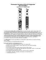
Controls and Jacks: Percussion Interface
IN Jack
The
IN
jack accepts a wide range of signals from microphones directed at acoustic
sounds such as drums, electronic drum machines, samplers, guitars, synthesizers,
line-level equipment, or any other audio source. With the exception of microphones
that require power (phantom-powered and electret microphones), any microphone or
piezo transducer will work. The
IN
jack is mono, but will work with a stereo or
balanced cable.
Sensitivity Knob and Light
The
Sensitivity
knob controls how much the input signal is boosted. At maximum
gain settings, the smallest input signal that will trigger a gate output is roughly 5–
10mV. The
Sensitivity
range is determined by the position of the
L|M|H
switch on
the
PI Expander
(see Setting Input Gain
section
on page 6
for more details). The
light will show blue when a signal is detected and will gradually turn red as the unit
begins to clip at the input. Clipping may result in undesired gates or envelopes, also
known as misfires. See Preventing Misfires and Undesired Gates on page 12.
Sustain Knob
The
Sustain
knob controls the pulse width of the gate output as well as the sustain
time of the envelope while in
Gen.
mode (see Envelopes in Gen Mode on page 8).
When the gate output is high no additional triggers will be generated, thus misfires
can be reduced. See Preventing Misfires and Undesired Gates on page 12. The
minimum pulse width is 5ms, and the maximum is 0.5s.
Envelope Decay Knob
The
Env. Decay
knob sets the decay time of the envelope. The envelope has an
exponential curve.
Follow/Gen. Switch
The
Follow/Gen.
switch selects between two envelope modes. In
Gen.
mode, the
envelope has a sharp attack, followed by a sustain period and an exponential decay.
The attack and sustain period are synchronized with the gate output, that is, the
envelope remains high as long as the gate is high. In
Follow
mode, the envelope
responds to the peaks and valleys of the input signal and ignores the gate. See
Envelopes in Gen. Mode on page 8 and Envelopes in Follow Mode
on page 9.
Gate Out Jack and LED Indicator
The
Gate
jack outputs a pulse which is generated from the input signal. It can be
used to clock sequencers and trigger other modules. When high, the
Gate
jack
outputs 8V, indicated by the white light above the jack.
Envelope Output Jacks
The top left jack, marked by the
+
symbol,
outputs a 0V to 9V envelope when
triggered by the input signal. The blue
light
above the jack indicates the envelope’s
level.
The jack at the bottom right, indicated by
the
–
symbol, outputs an inverted copy of
the
envelope. When the envelope is at rest,
this jack outputs 9V and the green light
above the jack is fully bright. When the
envelope is triggered, it falls to a minimum
of 0V and the green light will dim. This
envelope is useful for side-chaining (see
Sidechaining with the PI on page 14).
Page of
4
16
+
–
Gate
Env.
Out
IN
Gate
Env. Decay
Sustain
Follow
Gen.
Sensitivity
+ Env (blue) rests at 0V and sustains at +9V.
-Env (green) rests at +9V and sustains at 0V.


