


Page 14
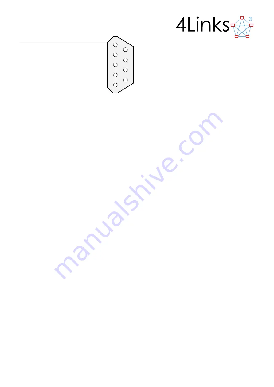
The pinout of the SpaceWire socket connectors (looking from the outside of the EtherSpaceLink unit) is shown
above:
All eight of these signals are buffered within the DSI using LVDS buffers for each of the differential signal pairs.
Within the DSI, all signal grounds are bonded to the chassis of the unit. Notice that the ground potential
difference between each device-under-test must be held within each receiver’s input common-mode voltage
range.
3.1.4
SpaceWire Time Codes
SpaceWire defines a mechanism for transferring a global time reference across a network. The DSI can display
time-codes that are received from the network. It can generate time-codes from the host computer. It is not
equipped with a hardware time-code generator; only the 4Links ESL (EtherSpaceLink) and ATI (Absolute Time
Interface) have one of these.
3.2
The Ethernet Connection
An RJ45 socket, housed in an SFP module situated on the front panel, supports 1000Mb/s (1000BaseT) or
100Mb/s (100BaseT) full-duplex Ethernet connections over twisted-pair cable. The interface has an auto-
crossover function, allowing direct connection of the EtherSpaceLink unit to a computer or to an Ethernet hub or
switch, using either a standard or a crossover cable.
3.2.1
ICMP Echo (ping) Support
The DSI will respond to an ICMP echo request - as provided on many operating systems via the
ping
command.
This can provide a simple test to check that the unit is accessible on the network.
3.2.2
Full-Duplex Ethernet
Only full-duplex Ethernet connections are supported.
3.3
SMA Synchronisation Connectors
Synchronization (to other 4Links units or to external devices) is achieved using SMA connectors, on units with the
“-S” model number suffix where they are fitted.
The rear panel of a suitably-equipped DSI contains eight SMA connectors, labelled J1 to J8 from left to right when
looking at the rear panel, corresponding to software and API synchronization connections J1-J8 respectively.
9
8
7
6
5
4
3
2
1
F
IGURE
3-1S
PACE
W
IRE CONNECTOR
P
INOUT