PAGE 51
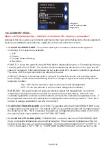
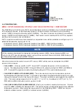
• 14.9.A PLUG ENABLED
- Choices are ON or OFF (default). A plug or choke sensor is usually used
for blocked chute detection. A Binswitch Elite is most commonly used however, an Auto-Set™ flush
probe can also be installed depending on the application.
When a plug sensor is installed and PLUG ENABLED is ON, the Watchdog looks for a change in
signal level representing the plug condition.
- ON: +24V into the terminal is seen as normal (no plug detected).
- OFF: 0V into the terminal is seen as blockage (plug) detected condition.
• 14.9.B PLUG TRIGGER ALARM WHEN
- Choices are ON or OFF (default). Allows you to choose
to trigger an alarm when the sensor contact is on, or trigger an alarm when the sensor contact is off.
The default is OFF, in order to switch this setting to ON, you must go to the FACTORY SETTINGS
menu.
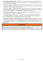
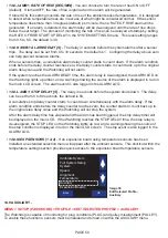
• 14.9.C PLUG ALARM DELAY [S]
- The delay in seconds before the system alarms after a sensor
trips. The delay can be set from 0 to 10 seconds, the default is 1. Configuring the delay above zero
can help prevent nuisance alarms.
When a sensors trips, a cumulative alarm delay counter starts to count down. If the alarm condition
ends before the delay counter reaches zero, the delay counter starts to count back up to the original
alarm delay value and the Watchdog will not alarm.
If the system reaches the ALARM DELAY time, the alarm relay is de-energized, the ALARM LED on
the Watchdog lights up amber, and a warning showing the source of the alarm is displayed in red on
the main LCD screen. The alarm event is also logged in the ALARM LOG.
• 14.9.D PLUG STOP DELAY [S]
- The delay in seconds before the system shuts down. The delay
can be set from 0 to 60 seconds, the default is 3.
A cumulative stop delay counter starts to count down simultaneously with the alarm delay. If the
alarm condition ends before the delay counter reaches zero, the counter starts to count back up to
the original stop delay value and the Watchdog will not stop the system.
After the alarm delay time has elapsed and the alarm has been triggered, the stop delay timer will
be displayed on the main LCD. If the Watchdog reaches the STOP DELAY time, the stop relay is
de-energized, the STOP LED on the Watchdog lights up red, and a warning showing the source of
the stop condition is displayed in red on the main LCD screen. The stop event is also logged in the
ALARM LOG.
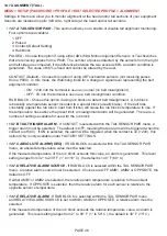
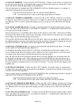
• 14.9.E PULLEY ENABLED
- Choices are ON or OFF (default). The pulley sensor is usually used
to detect if the drive pulley has moved position (misaligned). Typically a Touchswitch contact sensor
would be used for this application.
When a pulley sensor is installed and PULLEY ENABLED is ON, the Watchdog looks for a change in
signal level representing the misaligned pulley condition.
- ON: +24V into the terminal is seen as normal (no pulley movement).
- OFF: 0V into the terminal is seen when pulley movement has been detected.
• 14.9.F PULLEY TRIGGER ALARM WHEN
- Choices are ON or OFF (default). Allows you to choose
to trigger an alarm when the sensor contact is on, or trigger an alarm when the sensor contact is off.
The default is OFF, in order to switch this setting to ON, you must go to the FACTORY SETTINGS
menu.
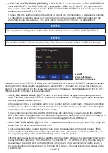
• 14.9.G PULLEY ALARM DELAY [S]
- The delay in seconds before the system alarms after a sensor
trips. The delay can be set from 0 to 10 seconds, the default is 1. Configuring the delay above zero
can help prevent nuisance alarms.
Summary of Contents for Watchdog Super Elite
Page 72: ...PAGE 72 END USER NOTES...
Page 73: ...PAGE 73 END USER NOTES...
Page 74: ...PAGE 74 PAGE 74 END USER NOTES...


