background image

15. TEST

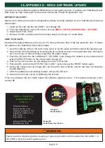
15. TEST -

MENU > SETUP (PASSWORD) > TEST

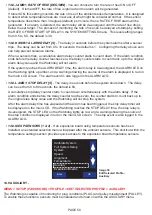
A number of test functions are available to simulate various fault conditions to validate the functionality 

of the alarm and stop relays (Image 37).  The testing function is not designed to test the sensors on the 

equipment, it allows you to ensure that your control wiring, PLC or HazardMon.com connectivity are 

functioning.  None of the tests will function if the Watchdog is in an alarm condition, or if the system has 

not been calibrated.  Testing can be run for the following:  ALARM RELAY, ALIGNMENT, OVER SPEED, 

Underspeed and HOT BEARING SENSOR.

Back

OK

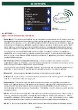
Image 37

Setup Menu - Test

Profile

Test
Factory Settings

SD Card

Time & Date

Change Password

Network

NOTE

Only the ALARM RELAY test can be started while the equipment is running.  All of the other tests 

require the equipment to be stopped prior to testing.

• 15.1 ALARM RELAY

 - Toggles the alarm relay 5 times at a rate of once per second.  The display 

prompts you to “Press OK to Start the Test and Then Start the Elevator”.  If the elevator is already 

running, the test will begin immediately.  If the elevator is stopped, the test will begin the next time 

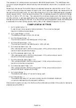
the elevator is started.  When testing begins, “ALARM TEST”  will appear under SYSTEM STATUS 

on the main LCD screen.  The elevator will remain running after the test is concluded.

• 15.2 ALIGNMENT

 - Simulates an alignment fault condition by introducing a head alignment fault.  

The values used for alarm and stop delays will be the current settings.  The display prompts you 

to “Press OK to Start the Test and Then Start the Elevator”.  The test will begin the next time the 

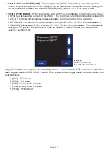
elevator is started.  When testing begins, “ALIGN. TEST”  will appear under SYSTEM STATUS on 

the main LCD screen.  The elevator will be in the stopped condition after the test is concluded.  If the 

alarm and stop delays are excessive, then it will take a long time to perform the test. 

• 15.3 OVER SPEED

 - Simulates an over speed fault condition by simulating an increase in speed 

by 15%, introducing an over-speed condition.  The values used for alarm and stop delays will be 

the current settings.  The display prompts you to “Press OK to Start the Test and Then Start the 

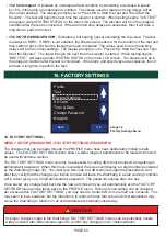
Elevator”.  The test will begin the next time the elevator is started.  When testing begins, “O/S TEST”  

will appear under SYSTEM STATUS on the main LCD screen.  The elevator will be in the stopped 

condition after the test is concluded.  If the alarm and stop delays are excessive, then it will take a 

long time to perform the test.

PAGE 59

Summary of Contents for Watchdog Super Elite

Page 1: ...o4b com usa Watchdog Super Elite BUCKET ELEVATOR BELT CONVEYOR HAZARD MONITORING SYSTEM INSTALLATION INSTRUCTIONS OPERATION MANUAL Part No s WDC4V4C WDC4V46C Hardware Version R4 Software Version 4 8 X...

Page 2: ...ing Diagram Profile with Rub Blocks Page 23 9 9 Sensor Wiring Diagram Profile with Motion Alignment Sensors Page 24 9 10 Sensor Wiring Diagram Profile with Knee or Idler Pulleys Page 25 10 WATCHDOG MA...

Page 3: ...n Monitoring Level Page 40 14 5 F Number of Starts Minute Page 41 14 5 G Start Up Delay Page 41 14 5 H Underspeed Enable Page 41 14 5 I Underspeed Alarm Page 41 14 5 J Severe Underspeed Page 41 14 5 K...

Page 4: ...G HBS Stop Delay Page 49 14 8 H AMB Page 49 14 8 I AMB Absolute Alarm Page 49 14 8 J AMB Rate of Rise Page 50 14 8 K AMB Alarm Delay Page 50 14 8 L AMB Stop Delay Page 50 14 8 M EXP Sensors Expansion...

Page 5: ...elay Page 55 14 10 E Analog Board 2AN Page 57 14 10 F Pt100 Board Page 57 14 11 Restore Defaults Page 58 14 12 Select New Profile Page 58 15 TEST Page 59 60 15 1 Alarm Relay Page 59 15 2 Alignment Pag...

Page 6: ...onal Electrical Codes and other standards applicable to your industry Please see the article Hazard Monitoring Equipment Selection Installation and Maintenance at www go4b com The installation of the...

Page 7: ...tion work at the facility hours of operation animal or insect infestation and the real world experience of knowing how your employees perform their jobs The personnel or person you select to install o...

Page 8: ...o notify users whenever a change in the system s health is detected An automated maintenance feature allows site operators to verify that all sensors on the system are operational and working correctl...

Page 9: ...temperature information from brass blocks to detect belt misalignment When the belt rubs against the brass block heat from friction is generated Alternative detection method not recommended due to unr...

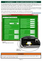
Page 10: ...e copied to another which is especially useful to duplicate settings on multiple controllers at the same location WDC4 CONFIGURATOR SOFTWARE The Watchdog Super Elite can be programed directly through...

Page 11: ...omponent or apparatus certified stopping plugs and cable glands conduit in strict accordance with the manufacturer s instructions In order to connect conduit to the control unit enclosure use a CSA an...

Page 12: ...ot shafts BELT MISALIGNMENT Qty 4 Sensors work in pairs one for each side of the belt on the drive and tail or head and boot sections PLUG INDICATION Qty 1 One sensor located near the top of the drive...

Page 13: ...so will invalidate the certification and any warranties which may exist Model WDC4V4C F1 F2 F3 F5 200 mA maximum F1 to F3 are used to limit the current available to the sensor inputs F5 is used to li...

Page 14: ...29 0 VDC 28 Bearing Sensor 6 27 Bearing Sensor 5 26 Bearing Sensor 4 25 Bearing Sensor 3 24 Bearing Sensor 2 23 Bearing Sensor 1 22 Ambient Sensor 2 21 Ambient Sensor 1 20 24 VDC Fuse F3 POWER RELAY C...

Page 15: ...or discharges HEAD DRIVE BOOT TAIL Plug Switch Optional Hot Bearing Sensor Hot Bearing Sensor Hot Bearing Sensor Hot Bearing Sensor Alignment Top Right Alignment Top Left Alignment Bottom Left Alignme...

Page 16: ...ction Watchdog Alarm Relay Watchdog Stop Relay Fuse 2 Amp Diagram A C Overload Motor Contactor Alarm Light Audible Warning Start Stop Motor Contactor Holding Contact L N AC Connection for Model WDC4V4...

Page 17: ...gnal to Feed Equipment Start Stop C1 C1 CR1 8 0 V 24 VDC CR1 6 7 8 9 10 11 12 13 14 15 16 N C N O COM N C N O COM 24 VDC Interlock Run Signal 120 to 240 VAC Supply Not Connected The Unit Must be Groun...

Page 18: ...t Stop Motor Contactor Holding Contact L N AC Connection for Model WDC4V46C 120 to 240 VAC 50 60 Hz Supply R1 WATCHDOG CONTROL UNIT 1 Alarm and Stop Relays are Shown Energized in the Normal Running Co...

Page 19: ...p Motor Contactor Holding Contact L N AC Connection for Model WDC4V46C 120 to 240 VAC 50 60 Hz Supply R2 WATCHDOG CONTROL UNIT 2 Alarm and Stop Relays are Shown Energized in the Normal Running Conditi...

Page 20: ...rom the factory defaults go to the EDIT SELECTED PROFILE menu 1 LEG TS 1 SP 4BS 4TS 1 Speed Sensor 4 Bearing Temperature Sensors 4 Touchswitch Sensors Alignment 2 LEG RB 1SP 4BS 4RB 1 Speed Sensor 4 B...

Page 21: ...l 1 35 0 VDC 34 Tail Rub Right T 10 33 Tail Rub Left T 9 3B 32 Tail Align Right 2B 31 Tail Align Left 5 1 30 24 VDC F2 WDC3 WDC4 WDC4 Terminal 29 0 VDC 28 Bearing Temp Sensor T 6 27 Bearing Temp Senso...

Page 22: ...Brown Red Blue X X RIGHT Orange Black White Red Green Blue Blue X X LEFT Orange Black White Red Green Alignment Bottom Tail Black Brown Red Blue X X RIGHT Orange Black White Red Green Blue Blue X X L...

Page 23: ...ue Brown Black White Speed P800 Alignment Top Head Brown Black Brown Blue Black Brown Alignment Bottom Tail Brown Black Brown Blue Black Brown RIGHT LEFT RIGHT LEFT Red Red 29 0 VDC 28 Bearing Temp Se...

Page 24: ...1 Plug Sensor 40 Head Rub Right T 12 39 Head Rub Left T 11 38 Head Align Right 37 Head Align Left 36 24 VDC F1 35 0 VDC 34 Tail Rub Right T 10 33 Tail Rub Left T 9 32 Tail Align Right 31 Tail Align Le...

Page 25: ...emp Sensor T 2 23 Bearing Temp Sensor T 1 22 Ambient Sensor 2 T 8 21 Ambient Sensor 1 T 7 20 24 VDC F3 Black Brown Black Brown Yellow Orange Bearing Bottom Tail Black Brown Black Brown Yellow Orange B...

Page 26: ...a menu tree to help guide you through all of the Watchdog s available menu screens and settings All new Watchdogs are preset to the factory default values Appendix B WDC4 Super Elite www go4b com Ini...

Page 27: ...temperature Disabled sensors are grey if a sensor is enabled it becomes highlighted in red green or amber Green signifies the sensor is in a normal state while red indicates an alarm Amber relates to...

Page 28: ...ed source detection method Refer to 14 5 for more detail about speed settings WARNING If the SD card is removed and more alarms occur they will not be logged when the SD card is re inserted For uninte...

Page 29: ...INFO 3 OF 9 The tail align info screen shows the tail alignment sensor type and the current values for the sensor The sensor type can be off pulsed contact CNT or rub block RUB The display will vary...

Page 30: ...such as those used with brass rub blocks ADB Series or surface temperature sensors WDB7 Series 10 10 EXP1 INFO 5 OF 9 EXP2 INFO 6 OF 9 If any of the optional expansion board s have been installed and...

Page 31: ...ary sensors PAGE 31 8 of 9 System Info Tue 04 Jul 2017 08 08 37 66 47 4 8 4 4 8 4 4 3 9 1836 Previous Next Exit Date Time Runtime Hours Main Version Graphics Version Btm Version DB Size Image 13 Syste...

Page 32: ...not be displayed This is a read only area no changes can be made within the VIEW SETTINGS menu Changes can only be made under SETUP or FACTORY SETTINGS which are password protected menus 11 VIEW SETTI...

Page 33: ...menu by choosing CHANGE PASSWORD The password is from 1 to 8 characters long and can be any combination of the letters A B and C If you change the password from the factory default make a note of you...

Page 34: ...w password it can be reset In order to perform a password reset you will need to contact 4B technical support and supply them with the four digit code displayed on the RESET ENG PASSWORD screen Image...

Page 35: ...ENU SETUP PASSWORD PROFILE EDIT SELECTED PROFILE Menu choices in this sub menu Image 21 include CALIBRATE SYSTEM FULL SYSTEM SETUP SYSTEM SPEED ALIGNMENT TEMPERATURE AUXILIARY and EXPANSION BOARDS Bac...

Page 36: ...of the system If the STOP button is operated on the motor starter interlock run signal removed during calibration the Alarm and Stop relays will be de energized and calibration will be aborted Calibra...

Page 37: ...PRE ABS ALARM Can be turned ON or OFF default If turned ON and the bearing temperature increases to within 10 F 5 C of either the RUB BLOCK ABSOLUTE ALARM section 14 6 C the HBS ABSOLUTE ALARM section...

Page 38: ...inches between each bucket and you wish to display speed in feet minute then set the scale factor to 9 This is a special case of when the scale factor is set to the bucket spacing in inches then the d...

Page 39: ...eed 2 For the differential speed option to work correctly it is necessary to enable alignment monitoring on either the tail and or head and for them to be set as Pulsed inputs The speed monitoring is...

Page 40: ...ation in speed 1 or if the belt begins to slip for any reason Because we know the ratio of speed 1 to speed 2 then we can check to see the amount of belt slip Example 3 Speed 1 is 350 PPM The ratio af...

Page 41: ...will cause an alarm The percentage can be set from 1 to 10 the default is 10 If the measured speed falls below the calibrated speed by this preset percentage the Watchdog will generate an underspeed...

Page 42: ...ediate stop of the elevator or conveyor 14 5 P OVERSPEED ALARM DELAY S The delay in seconds before the system alarms after a sensor trips The delay can be set from 0 to 10 seconds the default is 1 Con...

Page 43: ...as a belt misalignment condition RUB BLOCK Choose this option if using rub blocks to detect belt misalignment A rub block is basically a temperature sensor mounted to a special block usually brass If...

Page 44: ...o turn the rate of rise ON default or OFF If RELATIVE ALARM SOURCE is set to OFF you will not be able to choose RATE OF RISE If turned ON this setting monitors the rub block s rate of rise of temperat...

Page 45: ...ELAY S The delay in seconds before the system shuts down The delay can be set from 0 to 60 seconds the default is 60 A cumulative stop delay counter starts to count down simultaneously with the alarm...

Page 46: ...use the rub block s temperature to rise If the temperature rises above the preset limit a misalignment alarm will be generated There are a number of settings available for use with the rub block 14 7...

Page 47: ...M DELAY S The delay in seconds before the system alarms after a sensor trips The delay can be set from 0 to 10 seconds the default is 1 Configuring the delay above zero can help prevent nuisance alarm...

Page 48: ...ted Profile Temperature Back OK Calibrate System Full System Setup System Speed Alignment Temperature Auxiliary Expansion Boards Since the menus are the same for each NTC sensor HBS1 will be used as a...

Page 49: ...e alarm relay is de energized the ALARM LED on the Watchdog lights up amber and a warning showing the source of the alarm is displayed in red on the main LCD screen The alarm event is also logged in t...

Page 50: ...ng the source of the alarm is displayed in red on the main LCD screen The alarm event is also logged in the ALARM LOG 14 8 L AMB1 STOP DELAY S The delay in seconds before the system shuts down The del...

Page 51: ...conds before the system shuts down The delay can be set from 0 to 60 seconds the default is 3 A cumulative stop delay counter starts to count down simultaneously with the alarm delay If the alarm cond...

Page 52: ...reaches the STOP DELAY time the stop relay is de energized the STOP LED on the Watchdog lights up red and a warning showing the source of the stop condition is displayed in red on the main LCD screen...

Page 53: ...ng the expansion board s into the WDC4 note the location 1 or 2 as outlined in the board s installation manual Enter the EXPANSION BOARDS menu to select the board location 1 or 2 in the SETUP screen I...

Page 54: ...ashing editing cursor will appear under the first character pressing the left and right arrow buttons will move the cursor accordingly To edit simply press the up and down arrows to change the display...

Page 55: ...delay value and the Watchdog will not stop the system After the alarm delay time has elapsed and the alarm has been triggered the stop delay timer will be displayed on the main LCD If the Watchdog re...

Page 56: ...chosen since speed is being monitored This is can be changed based on individual requirements 2 CLI1 Input Range 4 to 20 The Milli Speed output is from 4 to 20 mA 3 CLI1 Min Scaled Value 0 The minimu...

Page 57: ...uts CLI1 CLI2 for 0 to 20 mA sensors to measure current Settings for the CLI inputs are similar to the ANALOG BOARD 6AN refer to 14 10 D for setup details 14 10 F Pt100 BOARD Pt100 board WDC4 AUXI 4Pt...

Page 58: ...All settings in the Watchdog can be restored to the factory default settings as described in Appendix B Before allowing the settings to be reset the user is prompted to enter the engineering password...

Page 59: ...elevator is started When testing begins ALARM TEST will appear under SYSTEM STATUS on the main LCD screen The elevator will remain running after the test is concluded 15 2 ALIGNMENT Simulates an alig...

Page 60: ...ETTINGS Back OK Image 38 Factory Settings Menu Profile Test Factory Settings SD Card Time Date Change Password Network 16 FACTORY SETTINGS MENU SETUP PASSWORD FACTORY SETTINGS PASSWORD The changes tha...

Page 61: ...4B recommends using the standard settings found within the PROFILE menu Refer to PROFILE for more details 16 2 RESTORE DEFAULTS MENU SETUP PASSWORD FACTORY SETTINGS PASSWORD RESTORE DEFAULTS The RESTO...

Page 62: ...load or save file operations have been completed remove the SD card and press the RESET button on the circuit board Image 47 to restart the Watchdog If the SD Card is missing or an error occurred duri...

Page 63: ...d Time Date Change Password Network 19 CHANGE PASSWORD MENU SETUP PASSWORD CHANGE PASSWORD In order to make any system changes to the Watchdog an engineering password is required This is to ensure tha...

Page 64: ...rk You can choose to turn DHCP ON or OFF default If you choose ON the network settings will be automatic If you choose OFF you will need to manually enter all of the network settings Ethernet IP Is th...

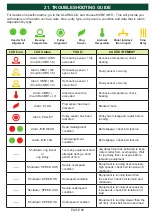
Page 65: ...ng Alarm MIS HEAD Head misalignment condition Belt slippage check belt tension Alarm MIS TAIL Tail misalignment condition Belt slippage check belt tension Shutdown Jog Event or Jog Delay Too many equi...

Page 66: ...ed refer to section 10 2 Wiring fault with stop relay or interlock run signal Equipment monitored and interlock run signal needs to turn off when stop relay opens EXP1ERR or EXP2ERR Expansion board is...

Page 67: ...gs Alignment Settings Temperature Settings Auxiliary Settings Expansion Boards Profile Test Factory Settings Password Req SD Card Time Date Change Password Network Edit Selected Profile Restore Defaul...

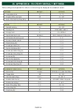
Page 68: ...S 5 1 15 Underspeed Alarm 10 1 10 Severe Underspeed 20 1 20 Underspeed Alarm Delay S 1 0 10 Underspeed Stop Delay S 60 0 60 Overspeed 10 1 10 Severe Overspeed 20 1 20 Overspeed Alarm Delay S 1 0 10 O...

Page 69: ...g 140 F 32 230 F AMB Rate of Rise Deg Min 3 0 0 5 5 0 AMB Alarm Delay S 1 0 10 AMB Stop Delay S 60 0 60 Some settings are dependent on others so not all may be displayed or available to select AUXILIA...

Page 70: ...then uploaded to the Watchdog by inserting the card into the System Card SD Card 1 slot Image 46 inside the control unit For remote sites the file can be emailed to an on site technician who can uplo...

Page 71: ...on the right hand side Be careful not to touch any of internal wiring especially the power supply 3 Place the SD card into the LANGUAGE SD CARD 2 slot Image 46 located on the inside lid and press the...

Page 72: ...PAGE 72 END USER NOTES...

Page 73: ...PAGE 73 END USER NOTES...

Page 74: ...PAGE 74 PAGE 74 END USER NOTES...

Page 75: ...USE ABUSE OR MISAPPLICATIONS AS AUTHORIZED BY LAW 4B SPECIFICALLY DISCLAIMS ALL WARRANTIES THAT THE PRODUCT IS FIT OR MERCHANTABLE FOR A PARTICULAR PURPOSE 3 NO WARRANTY BY SAMPLE OR EXAMPLE ALTHOUGH...

Page 76: ...COMPONENTS LTD Hunslet Road Leeds LS10 1JZ United Kingdom Tel 44 0 113 246 1800 Fax 44 0 113 243 5021 4B DEUTSCHLAND 9 Route de Corbie Lamotte Warfus e F 80800 France Tel 49 0 700 2242 4091 Fax 49 0 7...

Reviews: