


VISIX S-Series Network Camera
|
USER MANUAL v6.0
10385 Westmoor Drive, Suite 210, Westminster, CO 80021 | www.3xlogic.com | (877) 3XLOGIC
73
►
You need to reboot the camera if you want to turn on or turn off the
H.264+/H.265+ compression. If you switch from H.264+ to H.265+ directly, and
vice versa, a reboot is not required by the system
.
Profile:
Basic Profile, Main Profile and High Profile are selectable.
I Frame Interval:
Set the I-Frame interval from 1 to 400.
SVC:
Scalable Video Coding is an extension of the H.264/AVC standard. Select
OFF/ON
to
disable/enable the SVC function. Select
Auto
, and the device will automatically extract frames
from the original video when the network bandwidth is insufficient.
Smoothing:
Configure the smoothness, or fluency of the stream. The higher smoothing value, the
better fluency of the stream, though, the video quality may not be satisfactory. The lower the
smoothing value, the higher quality of the stream, though video may appear choppy and lack
fluency.
4.
Click
to save the settings.
CONFIGURING AUDIO SETTINGS
Steps:
1.
Enter the Audio settings interface:
Configuration >
Video/Audio > Audio
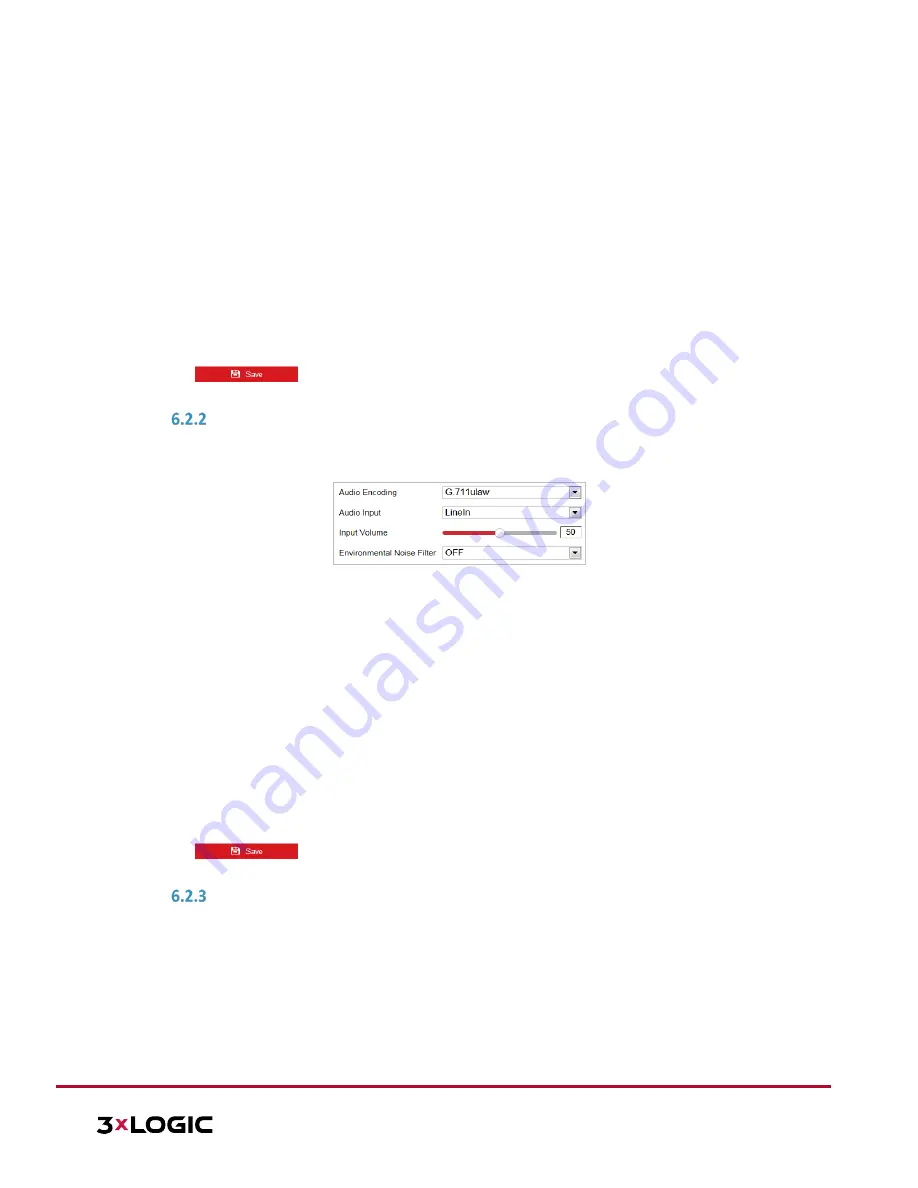
Figure 6-20
Audio Settings
2.
Configure the following settings:
Audio Encoding:
G.722.1, G.711ulaw, G.711alaw, MP2L2, G.726 and PCM are selectable.
Audio Input:
When an intercom is connected to the camera, you need to set this option to
LineIn
. When a microphone is connected to the camera, you need to set this option to
MicIn
.
Audio Stream Bitrate:
When the Audio Encoding is selected as MP2L2, you can configure the
Audio Stream Bitrate in the dropdown list. The greater the value is, the better the audio quality
will be.
Sampling Rate:
When the Audio Encoding value is set as MP2L2, you can configure the Sampling
Rate in the dropdown list. The greater the value is, the better the audio quality will be.
Input Volume:
Slide the bar to turn up/down the volume. The value ranges from 0 to 100.
Environmental Noise Filter:
Select
ON
or
OFF
in the dropdown list to enable or disable this
function. It is recommended to enable the function when the sampling rate is lower than 32 kHz.
3.
Click
to save the settings.
CONFIGURING ROI SETTINGS
Purpose:
ROI (Region of Interest) encoding is used to enhance the quality of images for a specified region. There are two
different ROI methods:
Fixed Region
and
Dynamic Region
.
When
Fixed Region
is enabled, image quality of the ROI area will be enhanced and image quality of other areas
will be reduced.
When
Dynamic Region
is enabled, image quality of tracking target will be enhanced.
NOTE:
ROI function varies depending on different camera models.