


Installation Manual
|
VISIX Network Camera
10225 Westmoor Drive, Suite 300, Westminster, CO 80021 | www.3xlogic.com | (877) 3XLOGIC
39
Steps:
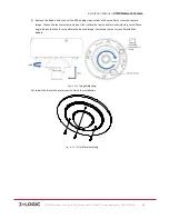
1)
Press the WPS button on the router.
2)
Press the WPS button (about 2s) on the camera within 120s of enabling the WPS on the router to join
the wireless network.
NOTE:
!
The WPS button works as a reset button only when you press it when the camera is powering
on.
!
Press the WPS button on the camera, and then press the WPS button on the router will
establish a connection as well, and the expire time of WPS connection on the camera is 120s.
!
The link indicator blinks if the wireless connection is succeeded.
AVAILABLE MOUNTS
!
MD Wall Mount (3xLOGIC Product #:
VX-‐WM-‐MD
)
!
MD Pendant Mount (3xLOGIC Prodcut #:
VX-‐PM-‐MD
)
!
Universal Corner Mount (3xLOGIC Product #:
VX-‐CM
)
!
Universal Pole Mount ( 3xLOGIC Product #:
VX-‐POLE
)
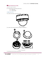
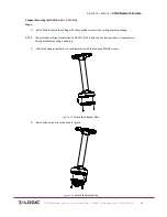
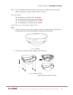
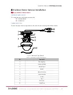
INSTALLATION OF TYPE II MINI-‐DOME CAMERA (TYPE A)
Steps:
1)
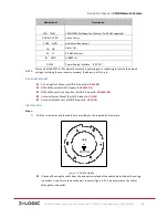
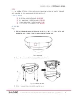
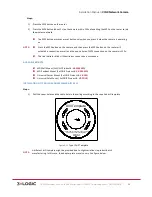
Drill the screw holes and the cable hole in the ceiling according to the supplied drill template.
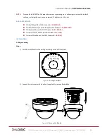
Figure 5-‐11
Type I Drill Template
NOTE:
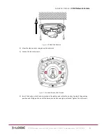
A different drill template might be provided due to slight variations in product batch
manufacturing. In this case, the adapter plate may also vary. See figure below.
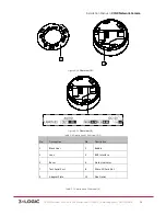
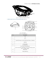
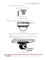
Drill Template
1
1
1
1
Hole A:for cables routed through the ceiling
Screw hole 1:for Mounting Base
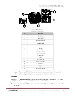
FRONT