


Installation Manual
|
VISIX Network Camera
10225 Westmoor Drive, Suite 300, Westminster, CO 80021 | www.3xlogic.com | (877) 3XLOGIC
33
5
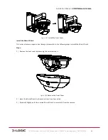
Mini-‐Dome Camera Installation
5.1
Type I Mini-‐Dome Camera
APPLICABLE CAMERA MODELS
This section applies to the following camera models:
!
VSX-‐2MP-‐MVD4
!
VSX-‐2MP-‐MVD28
!
VSX-‐2MP-‐MVD40
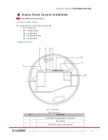
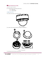
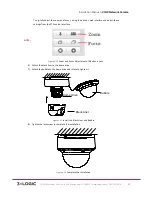
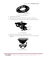
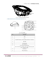
CAMERA DESCRIPTION
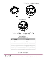
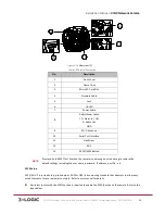
Figure 5-‐1
Overview
Physical Description
Table 1-‐8
No.
Description
1
Cover
2
Lens
3
Power LED indicator. Turns solid
red
when power is connected.
4
Base plate
5
Set screw hole
6
Set screw of lens
7
S & L: Network status indicator.
When the network is connected, the “S” LED is solid
yellow
, while the “L” LED flashes
orange
.
8
RESET Button