Installation Manual
|
VISIX Network Camera
10225 Westmoor Drive, Suite 300, Westminster, CO 80021 | www.3xlogic.com | (877) 3XLOGIC
58
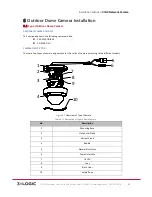
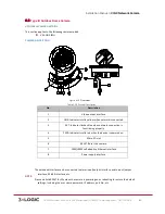
Description of Overview (1~2)
Table 1-‐12
No.
Description
No.
Description
1
Black Liner
6
Reset
2
Bubble
7
LAN(PoE) 10/100M Self-‐adaptive
Ethernet Interface
3
Mounting Base
8
Power Interface (DC 12v)
4
SD Card Slot
9
Lens
5
Video Out
10
Audio and Alarm Cables
Description of Audio and Alarm Cables Overview
Table 1-‐13
Label : Color
Description
CVBS : White
GND; Any Available
Auxiliary Monitor Output
RS485+ : Red
RS485-‐ : Yellow
RS 485
Interface
ALARMINA: Brown
ALARMINB: Orange
GND; Any Available
Alarm Inputs
OUT1A : Green
OUT1B :Blue
OUT2A :Purple
OUT2B : Green and White
GND; Any Available
Alarm Outputs
LINEIN_R: Orange and White
LINEIN_L/MIC: Yellow and White
LINEOUT_R: Gray
LINEOUT_L: Light Blue
GNDx2; Any Available
Audio
NOTE:
LINEIN_L/MIC
is the camera’s microphone input.
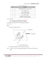
AVAILABLE MOUNTS
!
OD Wall Mount (3xLOGIC Product #:
VX-‐WM-‐OD2
)
!
OD Wall Mount w/ Junction Box (3xLOGIC Product #:
VX-‐WMJ-‐OD2
)
!
OD Pendant Mount (3xLOGIC Product #:
VX-‐PM-‐OD2
)
!
Universal Corner Mount (3xLOGIC Product #:
VX-‐CM
)
!
Universal Pole Mount ( 3xLOGIC Product #:
VX-‐POLE
)


