background image


   CLI user manual


(Figure 1.1.3) 

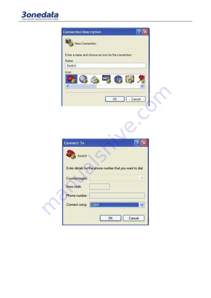
2) Choose connecting serial port. Choose connecting serial port under “Connect using”

pay 

attention to the chosen serial port is consistent with the port connected with the configuration 
cable) ,Click “OK”. As shown in Figure 1.1.4. 


(Figure 1.1.4) 

3) Set serial port parameters. As shown in Figure 1.1.5, set the “Bits per second” in the 
“Properties” of serial port is 115200bit/s, “Data bits” is 8, “parity” is None, “Stop Bits” is 1, 
“Flow Control” is None. Click “OK” button to enter to “Hyper Terminal” Window.   

Summary of Contents for IES7110-3G Series

Page 1: ...IES7110 3G series Managed Industrial Ethernet switches CLI user manual Version 1 0 0 Aug 2017 www 3onedata com ...

Page 2: ... marks in this manual belong to their respective manufacturers Agreement As the product version upgrades or other reasons this document is subject to change without notice Unless other agreement this document only as a guide to use All statement information and suggestion in this document without warranty of any kind either expressed or implied Revision History Version No Date Reason V1 0 0 2017 0...

Page 3: ...2 3 2 Display port configuration information 12 3 3 Port configuration 12 3 4 To enable or disable the port 13 3 5 Configure the port speed and duplex mode 13 3 6 Configure the port flow control 13 Chapter 4 Bandwidth Management 14 4 1 Enter rate management view 14 4 2 Egress bandwidth configuration 14 4 3 Ingress bandwidth configuration 14 4 4 Configuration of Type of ingress limited packets 15 4...

Page 4: ...n 28 10 1 Enter the port Trunk view 28 10 2 Port trunk configuration delete 28 10 3 Display port trunk configuration information 28 Chapter 11 The SNMP configuration 29 11 1 Configure the view into the SNMP 29 11 2 Enable the SNMP information 29 11 3 The SNMP configuration view 29 Chapter 12 Alarm configuration 30 12 1 Enter the alarm information view 30 12 2 Alarm configuration delete 30 12 3 Dis...

Page 5: ...me password settings 35 15 5 Display device IP subnet mask default gateway 35 15 6 Restore factory settings 36 15 7 The address of the DNS server settings 36 15 8 Obtain an IP address automatically set 36 15 9 Upload download the configuration file 36 15 10 The system upgrade 37 ...

Page 6: ...monitoring terminal equipment One end is RJ45 eight core plug the other end is the 9 hole plug DB9 Console RJ45 the switch socket head the cable inner connecting line diagram as shown below Figure 1 1 2 2 Configure terminal parameters 1 Turn the computer on the Windows interface click Start All Programs Accessories communication run a terminal emulation program to create a new connection The RS 23...

Page 7: ...is consistent with the port connected with the configuration cable Click OK As shown in Figure 1 1 4 Figure 1 1 4 3 Set serial port parameters As shown in Figure 1 1 5 set the Bits per second in the Properties of serial port is 115200bit s Data bits is 8 parity is None Stop Bits is 1 Flow Control is None Click OK button to enter to Hyper Terminal Window ...

Page 8: ...al attribute In the Hyper Terminal window select document property setting into the attributes settings window Select the terminal simulation of type VT100 or automatic detection click OK button to return to the hyper terminal window Figure 1 1 6 ...

Page 9: ...be displayed 1 2 Configuration through Telnet Terminal device use telnet connect to the switch through PC the requirements are as follows 1 The IP address of the switch can get it by search or modify Use IP command under the system management view 2 If PC and the switch in the same local area network the IP address must in a same network segment otherwise PC and the switch must cross router If sat...

Page 10: ... agreement table 1 3 1 as follow Table 1 3 1 Format Description Bold Key words of the command show by bold type italic Parameter of the command show italic type It shows part in is optical when command configuration is need x y It shows to pick up one from two or more items x y It shows to pick up one or no one from two or more items 2 Format agreement of figure interface Table 1 3 2 as follows Ta...

Page 11: ...ines aim at configuration of different functions First of all the switch establish connection then confirmation of user name and password finished after enter the correct user name and password enter help or in switch enter into system view Under the view of system corresponding view appears after typing indifferent command Table 1 4 1 system view command list View Function Prompt Enter Quit Syste...

Page 12: ...tion like trunking information Port_Trunk Trunk SNMP Snmp setting SNMP SNMP Alarm Setting Show or modify alarm information like power alarm port alarm etc Alarm_config Alarm Port Mirror Show or modify port mirroring information Port_mirror Mirror System Management Show or modify configuration information like IP address subnet mask default gateway and password etc System_manage Manage 1 4 2 Comman...

Page 13: ...dir Enter static multicast filters menu Information dir Enter device information menu 2 Type in a command and between there is a space if key word is in this location then type in all keywords and descriptions Example Switch information show Show mac Show device MAC Address Show version Show device version Show others Show device type name etc 2 Partial help 1 Type in a character string with It ca...

Page 14: ...nd lines port can provides the function similar to Dos key It automatic save command lines that users types in and users can use these history commands Detailed operating please check table 1 4 4 as follows Table 1 4 4 access history command Operating Key Result Visit previous history command Up If it exists earlier command it is taken out Visit next history command Down If it exists later command...

Page 15: ...e information command as table 2 2 1 Table 2 2 1 Operating Command Description Show system version show version Carry out under the view of device information Show MAC address of device show mac Carry out under the view of device information Show Device Type Name etc show others Carry out under the view of device information Configure device model name etc config Carry out under the view of device...

Page 16: ...pe command as follows and enter return key Switch information config n ABC123 OK 2 4 Delete device information Please reference table 2 4 1 Table 2 4 1 Operating Command Description Delete Device Type Clean t Carry out under the view of device information Delete Device Name Clean n Carry out under the view of device information Delete Serial Number Clean m Carry out under the view of device inform...

Page 17: ...r the port configuration view Table 3 1 1 to enter the port configuration view Table 3 1 1 Operating Command Description Enter the port configuration view port In view of the system under the 3 2 Display port configuration information Table 3 2 1 shows the command port configuration information Table 3 2 1 Operating Command Description Display port state information Show state portlist portlist 1 ...

Page 18: ...re the port speed and duplex mode Mode portlist 10h 10f 100h 100f 1000f auto portlist 1 3 5 10 or all mode 10h 10Mbps Half duplex 10f 10Mbps Full duplex 100h 100Mbps Half duplex 100f 100Mbps Full duplex 1000f 1000 Mbps Half duplex Auto Automated negotiation Example Rate of 3 4 5 100Mbps full duplex port configuration Switch Port Mode 3 5 100f OK 3 6 Configure the port flow control Table 3 6 1 to e...

Page 19: ...ress bandwidths not limit Table 4 2 1 Egress bandwidth configuration Table 4 2 1 Operating Command Description Egress bandwidth Config egrate portlist Bandwidth portlist 1 3 5 10 or all Bandwidth 128k 256k 512k 1M 2M 4M 8M 16M 32M 64M 128M 256M 0 unlimited Note only the Gigabit Ethernet port can be set larger than the bandwidth of 8M Example set the 1 port of egress bandwidth is 8M Switch Bandwidt...

Page 20: ...st 1 3 5 10 or all 0 1 2 3 Limit the packet type 0 All frames 1 Broadcast Multicast and flood unicast frames 2 Broadcast and Multicast only 3 Broadcast only Example set port 2 and port 1 entrance limit data All frames Switch Bandwidth config intype 1 2 0 OK 4 5 Displays the bandwidth configuration information Table 4 5 1 shows the bandwidth allocation information command Table 4 5 1 Operating Comm...

Page 21: ...Within a VLAN broadcast and unicast traffic will not be forwarded to the other VLAN helps to control the flow reduce equipment investment simplifying the management of network improve network security The switch supports 802 1Q VLAN and port based VLAN Port based VLAN 6 2 The contents of VLAN configuration The VLAN configuration including 1 show current VLAN type 2 VLAN Enable 3 configure the port...

Page 22: ...list vid VLAN ID 1 4095 portlist 1 3 5 10 or all 0 CPU port typelist UnModified UnTagged Tagged Delete Vlan Delete vidlist vidlist 1 4 5 4094 or all Example add VLAN of 2 a member of the port in 2 3 4 5 6 Switch Vlan Add 2 2 3 4 U VID 2 Port_cpu port 1 port 2 UnTagged port 3 UnTagged port 4 UnTagged port 5 port 6 port 7 port 8 port 9 port10 Tip This configuration will be validated after restarting...

Page 23: ... Command Description Pvid setting config pvid portlist pvid portlist 1 3 5 10 or all 0 CPU port pvid 1 3 5 10 or all 0 CPU port Port Type setting config type portlist Trunk Access portlist 1 3 5 10 or all Example setting port 2 3 and 4 PVID is 3 Switch Vlan Config Pvid 2 4 3 OK Tip This configuration will be validated after restarting ...

Page 24: ...delete command Operating Command Description Add multicast address Add macaddress portlist macaddress multicast address format is XY XX XX XX XX XX X is any hex number portlist Port 1 2 3 10 or all Delete multicast address Delete macaddress Example Add multicast address 01 22 33 44 55 66 its port members are Port 1 2 3 Multicast_filters add 01 22 33 44 55 66 1 2 3 MAC 01 22 33 44 55 66 Port 1 2 3 ...

Page 25: ...ollowing command to set the Dscp Cos enabled Table 8 2 1 to DScp Cos Operating Command Description Check Tos Cos check portlist 0 1 2 3 portlist Port 1 2 3 10 0 Forbid 1 use ToS 2 use CoS 3 all use Example Use CoS of Port 1 3 4 6 Switch QoS check 1 3 4 6 2 OK Example Use ToS of Port 2 3 5 6 Switch QoS check 2 3 5 6 1 OK 8 3 QoS queue configuration The user can use the following command to configur...

Page 26: ...y Low CoS value 2 priority Normal CoS value 5 priority Medium CoS value 7 priority Low 8 5 The default port priority allocation The user can configure a default port priority to use the following command Table 8 5 1 the default port priority allocation Operating Command Description The default port priority allocation Default priority portlist 0 7 portlist port 1 2 3 10 or all 0 7 Port priority Ex...

Page 27: ... manual 22 Operating Command Description To view the ToS CoS enabled state Show state portlist portlist port 1 2 3 10 or all To view the default port priority Show default portlist portlist port 1 2 3 10 or all ...

Page 28: ...e information view Operating Command Description Enter the ring network state information view Show ring To perform the operation in the system 9 3 To enable or disable the ring Users can use the following command to set the ring network enabled 9 3 1 ring network to set command Operating Command Description Ring opening Enable 1 2 3 4 1 Enable Ring1 2 Enable Ring2 3 Enable Ring3 4 Enable RSTP Rin...

Page 29: ...his configuration will be validated after restarting 9 5 The Ring2 configuration User can use the following command to configure Ring 2 after enabling it Ring2 configuration and modification Operating Command Description Configure Swring2 config ring2 1 2 ID Looptype port hellotime 1 2 Ring Group 1 Ring Group 2 id Ring ID value is 0 255 Looptype Ring type portlist Ring Port hellotime value is 0 30...

Page 30: ...escription Configuration Ring3 Config ring3 1 2 id LoopType port hellotime 1 2 1 ring group 1 2 ring group 2 id Said the ring network identification value of 0 255 LoopType Single Couple chain Daul_homing portlist Ring network port hellotime value of 0 300 Modify ring3 Modify ring3 1 2 options parameter 1 2 3 4 1 ring group 1 2 ring group 2 options H on behalf of Hellotime i ring network identific...

Page 31: ...0 24576 28672 32768 36864 40960 45056 49152 53248 57344 61440 hellotime RSTP hellotime Range 1 10 s delaytime RSTP delaytime Range 4 30 s maxage RSTP maxage Range 6 40 s Config rstp_port 1 2 3 4 5 6 7 G1 G2 G3 pathcost portpriority p2p edge enable pathcost Port pathcost Range 0 200000000 portpriority Port portpriority 0 16 32 48 64 80 96 112 128 144 160 176 192 208 224 240 p2p Port p2p no yes auto...

Page 32: ...t configuration Switch Ring Enable 4 OK Tip This configuration will be validated after restarting Switch Ring Config rstp_state 32768 2 15 20 OK Tip This configuration will be validated after restarting Switch Ring Modify rstp _state p 8192 OK Tip This configuration will be validated after restarting Switch Ring Config rstp_port 1 20000 128 auto yes yes OK Tip This configuration will be validated ...

Page 33: ... delete command Operating Command Description Configuration trunk Config 1 2 3 4 portlist 1 2 3 4 1 2 3 4 respectively mean trunk group1 2 3 4 portlist trunk port 1 2 3 10 or all Delete trunk Clean trunkgroup trunkgroup 1 2 3 4 respectively mean trunk group1 2 3 4 all All trunk group Example set the port 1 2 for the trunk group 1 Switch Trunk config 1 1 2 OK 10 3 Display port trunk configuration i...

Page 34: ...view Operating Command Description Show Snmp information Show To perform the operation in the system Close snmp Close Switch Snmp Show The only read community name public The read or write community name private The SNMP gateway 192 168 1 1 11 3 The SNMP configuration view The user can configure the SNMP using the following command Table 11 3 1 SNMP configuration command Operating Command Descript...

Page 35: ...erating Command Description Configure port alarm Port relay portlist enable disable portlist Alarm ports 1 2 3 10 or all Configuration power alarm Power relay 1 2 all enable disable 1 2 all Show the way power alarm 1 The first power supply 2 The second way power To turn off the alarm information Close alarm In view of the alarm type of Relay output configuration Type 0 1 0 1 type of relay output 0...

Page 36: ...ports 1 2 3 10 or all Show alarm output type Show type Run in view of alarm Example set the alarm information port Switch Alarm show port all Port 1 Alarm status Disable LOS Port 2 Alarm status Disable LOS Port 3 Alarm status Disable LOS Port 4 Alarm status Disable LOS Port 5 Alarm status Disable Link Port 6 Alarm status Disable Link Port 7 Alarm status Disable LOS Port 8 Alarm status Disable LOS ...

Page 37: ...ort Statistics configuration view Table 13 2 1 to enter the port statistical configuration view Operating Command Description Statistics port number and type Show frames port port 1 10 Clean up the count the number of frames Clean frames Example the port number and types of statistics 6 Switch Statistics show frames 6 InGoodOctets 243108 OutOctets 5252069 InbadOctets 0 OutUnicast 3732 InUnicasts 2...

Page 38: ... Table 14 2 1 port mirroring configuration delete command Operating Command Description Port mirroring configuration Config 0 1 2 mirror_port port 0 1 2 Data type 0 all data 1 Ingress data only 2 Egress data only mirror_port Mirror port 1 2 3 8 port Acquisition port Port mirroring delete Close mirror In view of the port mirroring Example the allocation of port 3 to collect all the data ports 1 and...

Page 39: ... can use the following command to set the system time Table 15 2 1 system timeout command Operating Command Description System timeout setting Set time_out time_out The system timeout value of 0 60 the unit minute a default timeout value of 5 minutes 0 Close timeout function Example set the system time is 10 minutes Switch manage set 10 OK The system is used to define the time when to enter the CL...

Page 40: ...rd settings Operating Command Description User name setting Hostname hostname hostname The user name string User password setting Password password password password The user password string 15 5 Display device IP subnet mask default gateway The following command to check the equipment available to the user IP subnet mask default gateway Table 15 5 1 devices IP subnet mask default gateway Operatin...

Page 41: ...ing Command Description DNS server DNS server To perform the operation in the system manage Switch Manage DNS 202 96 134 133 15 8 Obtain an IP address automatically set Table 15 8 1 DHCP enable setting Operating Command Description DHCP enable setting DHCP enable disable To perform the operation in the system manage Switch Manage DHCP enable Switch Manage DHCP disable 15 9 Upload download the conf...

Page 42: ...ll automatically exit 2 Super terminal and choose to upload the configuration file the suffix Cfg transfer Send the file browse Select the folder Users to upload the configuration file OPEN Use receiving protocol Xmodem Send 15 10 The system upgrade Through the super terminal users can upgrade the following command file system Before the upgrade please confirm the correctness of the file Table 15 ...

Reviews: