3M DFS 700 Installation And User Manual Download Page 64


Technical Information DFS 700 / 04.2009


7-10


1

2

3

4

5

6

7

8

Power

(4)


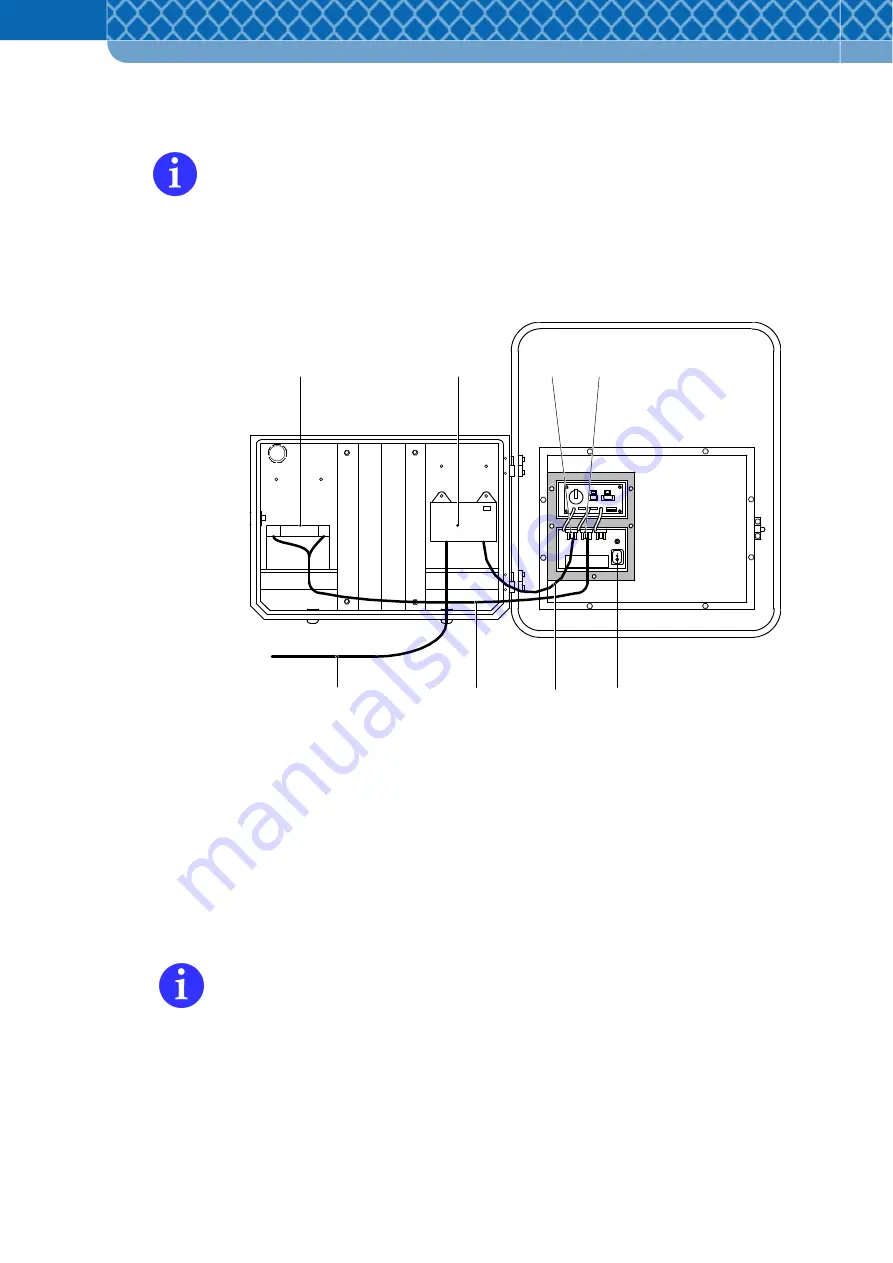
Switch on the DFS 700 at the switch (Figure 7-8 Item 5). 

After switching the DFS 700 on it performs a short self-check followed by the display 

of two horizontal bars "- -" as confirmation. In case of issues the display will show one 

of the codes explained in Section 9.4. 

(5)


Refit the service cover and close the DFS 700. 

(6)


Test the display function with a hand movement. 


Figure 7-8


Battery buffered mains operation 

The Battery is also charged even if the DFS 700 is switched off. 

A coloured LED on the Charger indicates the charge progress. 

If the LED lights up green, the Battery is fully charged and the charging 

process can be ended. 

The  Battery-charging  process  can  also  be  done  directly  from  the 

Charger without involving the DFS. 

For  compliance  with  CE  Regulations  for  fixed  installations,  where  the  Charger  is 

connected to the public mains network, a frequency filter has to be used in the supply 

line. Following types can be used: 

1. Schurter 5500.2034 FMLB-0109-2040 

2. Schurter 5500.2043 FMW2-52-2/1.25 

Summary of Contents for DFS 700

Page 1: ...3M Technical Information Installation and User Manual 3M Driver Feedback Sign DFS 700 ...

Page 2: ...ety Systems Division Carl Schurz Strasse 1 P O Box 10 04 22 D 41453 Neuss Phone 49 0 2131 14 7331 Fax 49 0 2131 14 3694 Email its eu mmm com Internet www 3M com de For questions please first contact your local dealer that you obtained your DFS 700 from All rights reserved 3M Deutschland GmbH Neuss 2008 ...

Page 3: ...ry work on the DFS 700 with optional accessories 6 4 6 4 Configuring the DFS 700 with a PC 6 8 6 4 1 Install the DFS CAS program 6 8 6 4 2 Install USB device driver for DFS 700 6 9 6 4 3 Connect DFS 700 and PC with the USB cable 6 10 6 4 4 Connect the DFS 700 and PC via Bluetooth adapter 6 11 6 4 5 Connect the DFS 700 and PC via GSM 6 12 6 4 6 Set up the DFS 700 with the DFS CAS program 6 13 6 5 C...

Page 4: ...4 Battery operation with one or two Batteries 7 11 7 3 5 Power supply to the GSM GPRS Modem 7 12 8 Analysis of Speed Data Measurements 8 1 8 1 Transfering measurements to PC or PDA 8 1 8 2 Assigning measurements to a location 8 2 8 3 Viewing measurements 8 3 8 4 Creating reports 8 4 9 Service and Maintenance 9 1 9 1 Cleaning 9 1 9 2 Maintenance 9 1 9 3 Symptom solution table 9 2 9 4 Diagnostic sta...

Page 5: ...no liability for operating faults or damage that arises as a result of failure to follow these operating instructions Particular subjects are highlighted as follows Working and operating procedures which have to be followed exactly so as to exclude life threatening injuries Working and operating procedures which have to be followed exactly so as to exclude danger to persons Working and operating p...

Page 6: ...Technical Information DFS 700 04 2009 1 2 ...

Page 7: ...more extensive use is deemed to be improper The manufacturer supplier is not liable for damages occurring as a result of this The user alone bears the risk Proper use also includes following the operating instructions and complying with the service and maintenance conditions 4 Keep the operating instructions within reach in the place where the device is installed 5 In addition to the operating ins...

Page 8: ...nal flashing lights etc This also applies to the fitting and adjustment of safety devices 13 Spare parts must meet the technical requirements specified by the manufacturer Only original 3M spare parts guarantee this 14 Only employ trained properly instructed and authorised personnel Clearly specify the responsibility of the personnel for operation and assessment Safety Tips for Operation 15 Refrai...

Page 9: ... 2 The electrical connections must always be produced in accordance with the requirements for the intended location In the case of fixed installations the plug on the power supply unit or the Charger may have to be removed If the plug is still to be used then an adequately waterproof weather resistant and properly mounted socket with protection to the power line as specified above is to be provide...

Page 10: ...ables This also applies to cable damage Battery if available 1 Do not remove the Battery pole caps A short circuit which can destroy the Battery is created by bridging the positive and negative poles with metal There is a risk of injury as a result of parts heating up or arcing voltages 2 The Battery cable and poles should be undamaged otherwise the Battery is to be replaced 3 As a basic principle...

Page 11: ...door use workshop office but inside the Battery Mounting Box it can also be used outdoors To avoid overheating do not cover the Charger during a charging cycle 3 The epoxy resin filled Charger is spray proof but must not be immersed in water for long periods IP67 4 The mains socket or a power disconnect must be easily accessible If an operating fault occurs remove the plug from the socket immediat...

Page 12: ...atters regarding the DFS 700 are defined by the current sales contractual conditions provided that legal regulations don t state otherwise Damages caused by improper installation or operation or as a result of excessive operational demands or the use of unsuitable product components is excluded from any kind of warranty and liability in all cases The equipment must only be used by properly trained...

Page 13: ...shorter with fixing cuffs and bolts 7 Power Supply Unit box 230 V with mounting plate optional accessory 8 Ventilation fittings 9 Rotary hinge for attachment to the optional Battery Mounting Box 10 Bolts for lock on the optional Battery Mounting Box 11 Top service cover 12 Bottom service cover 13 12 V connection cable for DFS 700 power supply from the Power Supply Unit box 14 Mains connector cable...

Page 14: ...nit 3 Mounting brackets with fixing cuff and bolts 2 sets bottom is shorter 4 Software CD with DFS CAS program for PC and PDA and this manual 5 Bluetooth Adapter with USB 2 0 plug CD with Bluetooth driver and operating instructions 6 USB connector cable On delivery please check for completeness and condition of parts In the event of complaints please contact 3M Customer Services see Section 1 1 2 ...

Page 15: ...ing instructions 12 V charging cable and mains connector cable 230 V see Safety Provisions Section 2 4 GSM GPRS Modem with mounting set 4A GSM Antenna 4B SIM card insert 4C Connector for GSM data cable 4D Connector for GSM power supply cable 5 EU Universal plug for connecting the Battery Charger only indoors 6 Power Supply Unit box with mounting plate 12 V power chord for DFS 700 and mains connect...

Page 16: ...Technical Information DFS 700 04 2009 3 4 ...

Page 17: ... of weather given the appropriate power supply As a result of the reflective sheet on the frame Figure 3 1 Item 1 the DFS 700 can be easily spotted by drivers during the day and especially in the dark due to reflection from the vehicle s headlamps If necessary additional information can be attached to the reflective area of the frame Figure 3 1 Item 1 4 2 Functionality In the ready to use state po...

Page 18: ...e PC by wireless connection A Bluetooth capable PDA can also be connected wireless to the display unit Where the optional GSM Modem Figure 3 3 Item 4 is used additional radio communication is possible via the GSM network mobile communication To that end a modem is needed in the PC and a GSM SIM card Figure 3 3 Item 4B is required in the GSM modem see also 4 5 The speed display unit has a 2 1 2 LED...

Page 19: ... light 4 USB plug connector 5 RS 232 plug connector for GSM GPRS Modem data cable 6 Flat fuse 4A delay action 7 Grounding bolts for connecting to a ground cable or a protective cable 8 DFS 700 on off main switch 9 Plug connector for optional 12V power from the 230 V Power Supply Unit box or second optional Battery is not powered by the Battery Charger 10 Plug connector for the first optional Batte...

Page 20: ...s standard model and with the optional accessory fittings using different possible power supplies Follow installation advices and electrical connections as specified in Section 6 Fixed installation with permanent power supply mains operation The standard model of the DFS 700 is used in a fixed location and is connected to the public electricity supply through the Power Supply Unit Additionally the...

Page 21: ...in periods of low traffic density or low relevance Standby Mode The DFS 700 operates with minimum power consumption which only allows the equipment to be configured using the user program Radar and Display are inactive Radar Mode The speeds of approaching vehicles are measured and displayed and the speed data is stored Limit Mode Like Radar Mode with the difference that a user defined speed limit ...

Page 22: ...anagement system of the DFS 700 cuts the DFS 700 off from the Battery at a voltage under 10 8 V so as to avoid deep discharge If the optional GSM GRPS modem is fitted and active an error message concerning the imminent low Battery level is sent by SMS to the specified recipient The Battery is safely housed and protected from weather in the optional Battery Mounting Box Figure 3 3 Item 1 For separa...

Page 23: ...ed 1 Schurter 5500 2034 FMLB 0109 2040 2 Schurter 5500 2043 FMW2 52 2 1 25 GSM GPRS Modem The GSM GPRS Modem Figure 3 3 Item 4 specially for the DFS 700 is a mobile communication modem for transmissions over any distance An activated SIM card with data services Circuit Switched Data Services is required for mobile communication to the DFS 700 Figure 4 2 GSM SIM card This SIM card must be obtained ...

Page 24: ...r Bluetooth connections for using the same functions of the software download data diagnostics etc For mobile communication a modem must also be installed in the PC for dialling into the DFS 700 Figure 4 3 GSM connection from PC to DFS 700 The GSM GRPS Modem is supposed to be installed into the Battery Mounting Box since it provides particular protection for the modem It can also be installed in a...

Page 25: ... case can be locked with a key Figure 4 4 Item 5 Interior ventilation is provided by the two vents in the rear wall The vents must not be covered and must always be kept open The Batteries can be placed on the two trays Figure 4 4 Item 4 Fixings and bolt threads are already in place on the back for attaching the GSM GPRS Modem Figure 4 5 Item 2 the Battery Charger Figure 4 5 Item 3 and the Power S...

Page 26: ...box Figure 4 5 Item 6 or Battery Charger Figure 4 5 Item 3 Figure 4 5 Positions of accessories and components 1 Opening for GSM antenna 2 GSM GPRS Modem 3 Space for Battery Charger 4 Battery 5 Openings for PG screwed joints 6 Power Supply Unit box or Battery 7 Ventilation opening Only a qualified electrician may carry out this work Risk of injury as a result of electric shock The Battery Mounting ...

Page 27: ...o be protected by a soft cover For transport all outward leading cables are to be laid such that they cannot hang loose The Battery must be removed from the Battery Mounting Box prior to transport and packed separately Follow safety advices on handling the Battery see Section 2 During transport do not hit the parts or subject them to strong vibration 5 2 Storage The DFS and its accessories switche...

Page 28: ...Technical Information DFS 700 04 2009 5 2 ...

Page 29: ...Driver USB Bluetooth Bluetooth Driver Power 6 Preparation and Configuration 6 1 Overview of first comissioning These images show the sequence of the first use up to operation of the standard model DFS 700 Figure 6 1 and DFS 700 with optional accessories Figure 6 2 in simplified form The individual working steps are listed and explained in detail in the following sections Figure 6 1 Commissioning D...

Page 30: ...ndows 2000 XP PDA GSM Bluetooth Bluetooth Driver Telephone PC CD DFS CAS Windows Mobile PDA USB or and Preliminaries Configuration with PC Configuration with PC and PDA Operation Power Power Power Power USB Driver Figure 6 2 Commissioning DFS 700 with optional accessories ...

Page 31: ... fully Figure 6 3 Item 3 and check if the mounting bracket is seated securely 3 Set the fixing plate Figure 6 3 Item 5 of the optional Power Supply Unit box Figure 6 3 Item 6 centrally in the frame on the top side and insert the two clamps Figure 6 3 Item 7 4 Tighten the two hexagonal nuts fully Figure 6 3 Item 8 and check if the Power Supply Unit box is seated securely If required the Power Suppl...

Page 32: ...with the free mounting plate holes Figure 6 4 Item 3 onto the two bolt threads Figure 6 4 Item 4 on the left in the Battery Mounting Box and tighten fully with two M4 hexagonal bolts Figure 6 4 Item 2 Figure 6 4 Fitting the Power Supply Unit box 2 Create an opening in the base of the Battery Mounting Box for the power cable Figure 6 4 Item 5 and pull the power cable through the opening which shoul...

Page 33: ...of the Battery Mounting Box and tighten fully with two M4 hexagonal bolts Figure 6 4 Item 1 2 Create an opening in the base of the Battery Mounting Box for the power cable Figure 6 5 Item 4 and pull the power cable through the opening which should be sealed with a PG seal Only qualified electricians are allowed to carry out this work see safety advice in section 2 Risk of injury from electric shoc...

Page 34: ...ing Figure 6 6 Item 4 The cover protects the GSM Modem from dripping condensed water 3 On the GSM GPRS Modem Figure 6 6 Item 10 insert the clips Figure 6 6 Item 2 into the rear rail from both sides and adjust the spacing so that the GSM GPRS Modem can be seated on the two bolt threads The antenna connection Figure 6 6 Item 16 must point to the left Fix the GSM Modem in place with two M4 fixing scr...

Page 35: ... tightly to the antenna connection Figure 6 6 Item 13 7 Screw the data cable Figure 6 6 Item 12 to the RS 232 interface Figure 6 6 Item 14 8 Plug the power cable to the DFS 700 into the socket Figure 6 6 Item 15 9 Collect excess cable and tie off with cable ties 10 Insert an activated GSM data SIM card into the SIM card holder Figure 6 6 Item 16 in the GSM GPRS Modem and lock it See Section 4 5 fo...

Page 36: ...P4 or Windows XP SP2 operating system Internet Explorer 5 0 Installation 1 Insert the program CD in the drive the Setup program starts automatically 2 Select Install DFS CAS for Windows or select Start then Run from the Windows taskbar and enter the path to the CD ROM drive and the setup program file name e g d setup exe to open it 3 Click OK to confirm The program is installed in doing so follow ...

Page 37: ...ogram CD in the drive the Setup program will start automatically 2 Install Install USB Driver or select Start then Run from the Windows taskbar and enter the path to the CD ROM drive and the program start file e g d USB PDInst exe in the Run window 3 Click OK to confirm The USB driver is installed in doing so follow the installation instructions and when asked connect the DFS which needs to be swi...

Page 38: ...ch on the DFS 700 at the main switch Figure 6 8 Item 6 After switching the DFS 700 on it performs a short self check followed by the display of two horizontal bars as confirmation In case of issues the display will show one of the codes explained in Section 9 4 5 Insert the rectangular plug of the USB cable Figure 6 8 Item 7 into the USB socket Figure 6 8 Item 2 6 Insert the USB cable with the fla...

Page 39: ...onment DFSAA09580906 5 Right click with the mouse on the device symbol and create a paired connection The Bluetooth PIN of the DFS unit is initially 0000 for security reasons change it later see Section 6 4 6 If successful a red check symbol appears next to the device symbol Create paired connection The paired connection remains permanent and only has to be renewed if the Bluetooth PIN changes or ...

Page 40: ...ut immediately after the dial command character sequence e g atd followed by 0 Figure 6 9 Connection settings for modem 5 All other steps to communicate with and configure the DFS 700 are to be carried out as described in Section 6 4 6 As part of this a dial in number must be entered in the DFS list for the DFS to be dialled see Figure 6 14 without using special characters or the national dial pre...

Page 41: ...e main screen containing the DFS list and the Location list appears Figure 6 10 DFS list and Location list 2 Open the Options General window via Settings Here several general parameters can be set as required A text which then appears on all printout pages can be entered in Caption for printout A path to your own Logo in wmf Windows Meta File format which then appears on the graphical printouts ca...

Page 42: ...s select the USB connection and select Edit Figure 6 12 DFS CAS connections 4 Select the COM port to which the USB cable is connected in the DFS CAS connection parameters window The correct COM port can only be selected if the DFS is switched on and connected to the PC s USB port The COM port may possibly change at the next use ...

Page 43: ... entries The DFS ID has to be specified by the user and must be different from any other entries in the DFS list If a GSM Modem is used the data service call number of the GSM SIM card is to be entered in the Dial number field see Section 4 5 In doing so only use digits and not special characters and also omit the national dial prefix if calling from the same country Figure 6 14 Add Edit DFS COM15...

Page 44: ...ist and make the required entries The location name has to be specified by the user and must be different from any other locations in the Location list Figure 6 15 Add Edit location 6 Open the window Parameter Source using the command DFS Parameters for the DFS selected in the DFS list Select the option shown in the Figure below Figure 6 16 Parameter source ...

Page 45: ...eneral Display Operating Mode Radar Wireless Communication where the parameters are to be user defined in sequence The data and names of the input fields are self explanatory Selection elements with preset texts can be changed by clicking on them Commands which cannot be performed in the respective window are shown in grey Active commands are shown in black After the modification the settings can ...

Page 46: ...700 system time can be set or synchronised with the PC time in the General tab The time can only be changed if this does not affect existing traffic data entries Data may have to be downloaded and erased before the time can be changed Figure 6 18 General ...

Page 47: ... for data analysis in the program options Measure and log speeds from to Enter the speeds between which the DFS 700 measures and records Speeds above and below the set range are not measured and not stored Display Green Red from to Enter the speeds between which the digital displays in green red Both colour ranges are fully independent of each other If the ranges overlap green and red are displaye...

Page 48: ...imum permissible speed In order to display the speed limit only above a certain speed the colour range has to be set accordingly For example if the unit is supposed to display a red 50 above speeds of 55 km h then the following settings are suitable Measure from 3 to 198 measure and store all Green from 199 to 199 is never displayed Red from 55 to 199 activate red above 55 km h Display in speed li...

Page 49: ...ection 4 4 Standby Mode Communication only Radar Mode Display the currently measured speed Covert Mode Store the speed only No display Limit Mode Display a fixed value e g speed limit Demo Mode Display random numbers All 27 possible switching programs are deactivated on delivery and can be configured as required Thereby days times and change to Standby mode or the selected mode can be defined In c...

Page 50: ... 22 11 The radar sensitivity can be set as required in the Radar tab The maximum setting 255 is advisable Reducing the sensitivity is only recommended in the case of faulty measurements caused by adverse ambient conditions Figure 6 21 Radar ...

Page 51: ... can be cut again The Bluetooth PIN is 0000 on delivery and should be changed for security can only be done via USB connection Write the new PIN down and keep it in a safe place If the new PIN is lost it can be reset to 0000 by restoring the DFS to the factory settings GSM Modem PIN on the DFS The PIN number of the data SIM card which has to be inserted in the optional GSM Modem if available see S...

Page 52: ... empty Status code in the event of issues Self test every 24 hours see chapter 9 4 SMS Service Centre Enter the SMS Service Centre call number of the mobile phone operator who supplied the data SIM card see Section 4 5 13 The DFS 700 is now ready for use As a simple function test an open hand can be waved quickly past the radar sensor of the DFS 700 if the speed display is set low enough the speed...

Page 53: ...C Requirements PC with Intel Pentium III CD ROM drive Windows 2000 SP4 or Windows XP SP2 operating system Internet Explorer 5 0 Display Monitor resolution 1024 x 768 Microsoft Active SynC 4 2 or higher 20 MB free disk space At least 256 MB RAM working memory Installation 1 Insert the program CD in the CD ROM drive the Setup program then runs automatically 2 Select Install DFS CAS for Windows Mobil...

Page 54: ...en PC and DFS 700 see Section 6 4 4 2 Search Bluetooth environment DFSAA09580906 6 Create paired connection The Bluetooth PIN of the DFS unit is initially 0000 for security reasons change it later see Section 6 4 6 The paired connection remains permanent and only has to be renewed if the Bluetooth PIN changes or either the PDA or the DFS breaks the paired connection 7 Select the Serial Port connec...

Page 55: ...way from large traffic signs Otherwise these large traffic signs can reflect the radar beams such that the vehicles in the opposite lane could be recorded by the radar beam Do not set the DFS 700 up directly at crossing intersections or bridges The DFS 700 must be at least 125 metres away from crossing traffic as it could otherwise also record the crossing traffic as oncoming vehicles Where solar ...

Page 56: ...rson For tightening only commercially available tools are required 7 2 1 Standard model DFS 700 1 At the selected location place the pre mounted DFS on the ground with its two mounting brackets Figure 7 1 Item 1 on a fixed pole that is 60 mm in diameter and has been tested for a secure and stable stand Figure 7 1 Item 6 2 Place the pole clips Figure 7 1 Item 2 on the two mounting brackets around t...

Page 57: ...erwise slip downward There is the risk of injury 4 Rotate the DFS 700 horizontally such that the radiated beam lies over the carriageway to be monitored see Figure 7 2 The maximum horizontal angle of rotation should be below 10 5 Tighten the joints If necessary secure the DFS 700 from slipping by a clamp on the fixing pole or a transverse bolt In the case of a longer set up time after approx 2 day...

Page 58: ...metres centrally above the lane to be monitored The fixing pole holding the DFS 700 must be vertically tiltable so as to align the DFS 700 to the lane Tilt the DFS 700 vetically such that the radiated beam lies over the carriageway to be monitored see Figure 7 3 The vertical angle of tilt should be 6 to 8 downwards Figure 7 3 Aligning the DFS 700 above a road 4 6m max 6 to 8 24 14 ...

Page 59: ...gure 7 4 Item 5 3 Set the casing on a fixed pole that is 60 to 140 millimetres in diameter and has been tested for a secure and stable stand Press the clamping plate around the pole back into the casing Loosely screw the four hexagonal nuts onto the threaded bolts 4 If provided place an already charged Battery in the casing 5 When setting up beside a road push the Battery Mounting Box two metres u...

Page 60: ... the Battery Mounting Box is mounted in a fixed position above the road e g on a signal bridge it must be located centrally at a height of 4 to 6 metres above the lane to be monitored The fixing pole holding the mounted Battery Mounting Box must be vertically tiltable so as to align the DFS 700 with the lane Tilt the box vertically such that the radiated beam lies over the carriageway to be monito...

Page 61: ...nected via the over current protective device The over current protective device is to be installed in accordance with the local electrical guidelines and safety requirements Therefore in Scandinavia for example a cut out must have a 2 pole connection against grounding The electrical connections must always be produced in accordance with the requirements for the intended location In the case of fi...

Page 62: ... Connect the mains cable Figure 7 6 Item 2 from the Power Supply Unit box to the mains 3 Switch on the DFS 700 at the switch Figure 7 6 Item 4 After switching the DFS 700 on it performs a short self check followed by the display of two horizontal bars as confirmation In case of issues the display will show one of the codes explained in Section 9 4 4 Refit the service cover 5 Test the display funct...

Page 63: ...Mounting Box 7 3 3 Buffered mains operation with Battery and Charger The Battery to be used in this configuration should be fully charged in advance 1 Remove the lower service cover on the open DFS 700 and insert the power supply cable Figure 7 8 Item 6 from the Charger Figure 7 8 Item 2 into the left hand plug Figure 7 8 Item 3 2 Insert the cable Figure 7 8 Item 8 of the Battery Figure 7 8 Item 1...

Page 64: ...gure 7 8 Battery buffered mains operation The Battery is also charged even if the DFS 700 is switched off A coloured LED on the Charger indicates the charge progress If the LED lights up green the Battery is fully charged and the charging process can be ended The Battery charging process can also be done directly from the Charger without involving the DFS For compliance with CE Regulations for fix...

Page 65: ... 9 Item 7 2 If available insert the cable Figure 7 9 Item 4 of the second Battery Figure 7 9 Item 2 into the right hand plug Figure 7 9 Item 7 3 Switch on the DFS 700 at the switch Figure 7 9 Item 5 After switching the DFS 700 on it performs a short self check followed by the display of two horizontal bars as confirmation In case of issues the display will show one of the codes explained in Sectio...

Page 66: ...y cable Figure 7 10 Item 6 into the connection socket of the GSM modem Figure 7 10 Item 7 and the other plug into the socket on the DFS Figure 7 10 Item 3 4 Connect the GSM data cable Figure 7 10 Item 5 to the sockets on the DFS and GSM Modem Figure 7 10 Item 8 and 4 and tighten them Figure 7 10 Connect the GSM GPRS Modem 5 Approx 10 seconds after switching on the DFS 700 the LED on the side of th...

Page 67: ...ata from the DFS 700 to PC establish a USB Bluetooth or GSM connection see Section 6 4 2 Start the DFS CAS program highlight the device to be read in the DFS List and open the download window via the Read DFS data command Figure 8 1 Read data from DFS A data storage path is suggested as standard here for the data to be read It can be changed if required The suggested path is located in the data fo...

Page 68: ...software Highlight the appropriate location in the Location List and open the Read data from file window via Location and Assign data 2 Select and open the freshly downloaded dat file in the data directory the data will be allocated to the selected location Figure 8 2 Load data from file While assigning data downloaded from a DFS to a location new files wer created in a sub folder of the data fold...

Page 69: ...sly assigned to a selected location can be viewed in the Measurements window via the View measurements command Figure 8 3 View measurements 2 All measurements for a selected day and selected time period are listed after pressing View Here individual measurements can be checked if needed ...

Page 70: ...n in order to analyse all assigned data statistically 1 Select and mark the location in the Location List 2 Open the Data report window via the Create report command The data report window consists of three areas from left to right the data selection area the report table area the chart buttons Figure 8 4 Data report ...

Page 71: ...erent graphs by pressing one of the buttons on the right of the window All graphic charts can be printed via the functions of the menu bar In the print view and on printing the logo specified in Options is shown Measurement quantity over reporting period button This chart shows the number of measurements over time for the selected reporting period The time interval is defined in the Data report wi...

Page 72: ... interval is specified in the Data report window Figure 8 4 Figure 8 6 Measurement quantity over daytime bins Speed stats over reporting period button This chart shows the maximum speed the mean speed and the n th percentile speed e g v85 over time for the selected reporting period The time interval is defined in the Data report window Figure 8 4 Figure 8 7 Speed stats over reporting period ...

Page 73: ...rting period The time interval and desired percentile are defined in the Data report window Figure 8 4 Figure 8 8 Speed stats over daytime bins Measurement quantity over speed bins button This chart shows the number of measurements relative to speed intervals for the selected reporting period The speed interval is preset in the Data report window Figure 8 4 Figure 8 9 Measurement quantity over spe...

Page 74: ...all measurements which stayed under a specific speed In v85 this means 85 of all vehicles stayed under this speed Figure 8 10 Speed over measurement percentage Statistics over weekdays button This chart shows the maximum mean and v85 speeds and the number of measurements over weekdays for the selected reporting period The report period and the desired percentile are defined in the Data report wind...

Page 75: ...es the displays of Figure 8 6 and Figure 8 9 It shows in three axes the number of measurements related to time of day and speed intervals for the selected reporting period according to the defined speed and time intervals in the Data report window Figure 8 4 Figure 8 12 Measurement quantity over daytime and speed bins ...

Page 76: ...Technical Information DFS 700 04 2009 8 10 ...

Page 77: ... a visual inspection and while doing so pay particular attention to the condition of the mains cables These must not be damaged but if they are have the cable replaced by a qualified electrician If Batteries are used check that their external condition is perfect in advance In case of damage replace the Battery When handling bateries pay particular attention to further safety advices as specified ...

Page 78: ...by Chose radar mode in the operating mode settings DFS 700 is switched off Switch on DFS 700 No power to DFS 700 Check power supply Operating mode settings are limit mode or standby Chose radar mode in the operating mode settings DFS 700 fuse failed Check DFS 700 fuse DFS 700 does not show any reaction Wrong configuration parameters are chosen Check configuration parameters Wrong configuration par...

Page 79: ...ry or charger Change cable Battery is connected at connection Battery 2 Connect battery at connection Battery 1 Battery is not charged again Power of solar panel is to low Solar panel is placed in shadow or the size of the panel does not deliver the needed power Very high volume of traffic Use second battery LED brightness range settings are very high Select lower LED brightness in the configurati...

Page 80: ...r Settings are made for only one color Specify the second color in the configuration settings Operating mode settings are limit mode Chose radar mode in the operating mode settings Only one speed value is displayed Wrong configuration parameters Check configuration parameters Operating mode settings are limit mode Chose radar mode in the operating mode settings Large objects reflecting the radar w...

Page 81: ...with different numbers for each service Wrong PIN code Check SIM PIN code Pre paid card is out of credit Recharge pre paid card No or busy phone line Connect phone line to your modem and try to dial up several times GSM connection cannot be made No modem connected to PC or wrong configuration Connect a modem to your PC and check for correct COM port and config USB device driver is not installed In...

Page 82: ...etup program is in a deep folder Start setup program from another folder e g C temp Name of the setup folder includes a blank Check setup folder name and choose different PDA Software cannot be installed Wrong version of ActiveSync on your PC Download and install ActiveSync Version 4 2 Rubber seal has sliped Check rubber seal on your mounting box Cables are between the rubber seal and the DFS 700 ...

Page 83: ...Technical Information DFS 700 04 2009 9 7 ...

Page 84: ... SMS to a defined mobile phone number see section 6 4 6 This function requires the use of the optional GSM Modem and the availability of a SIM card with data servicesfrom a local GSM supplier see section 4 5 Diagnostic Information and additional device information can be obtained from the DFS anytime using the Status command in the PC oder PDA software The following additional information can be o...

Page 85: ...ommunication to real time clock 9 9 10 Battery for real time clock empty 10 10 10 11 Diplay defect 11 11 11 64 SIM not inserted 64 65 SIM PIN or PUK is missing 65 66 SMS transmission not successfull 66 67 GSM connection not successfull 67 70 SIM PIN is wrong 70 80 Bluetooth connection not successfull 80 81 Wrong Bluetooth PIN 81 Start diagnostics finished 9 5 Firmware update The firmware is the co...

Page 86: ... active components Fuse ATO 4A Delay Action Fuse Case ingress protection IP 54 Case colour RAL 7042 Permissible ambient temperature in the casing 35 to 75 C Permissible humidity up to 95 Digital display 330 mm high 450 mm wide 2 1 2 digital display with 13 segments highest displayable value 199 LEDs InGaAIP SMD LEDs Viewving angle 16 to 18 3 rows green LEDs 570 mm 3 rows red LEDs 635 mm Buffer bat...

Page 87: ...y 2 Main switch RS232 socket for GSM Modem GSM power supply Activation switch for external devices Grounding bolt Activation switch Max 24 VAC DC Max 150 mA plug type Weidmüller BLZF 3 5 3 F SNOR Control program Firmware updatable Fixing Frame Reflective coating Diamond Grade white Printable surface 53 cm wide 29 cm high Power Supply Unit Box optional equipment Input 100 V 240 VAC 50 60 Hz Protect...

Page 88: ... Input 100 V 240 VAC 50 60 Hz Protection Class 2 Output max 12 V 60 W Ingress Protection IP 67 Temperature range 40 to 40 Weight approx 1 0 kg Battery Mounting Box optional equipment useable pole diameter 60 to 140 mm horizontal inclination after installation 2 Weight empty 7 5 kg Control and Analysis Program software for Windows 2000 XP PC DFS CAS Control and Analysis Software for Windows Mobile ...

Page 89: ...Technical Information DFS 700 04 2009 10 4 ...

Reviews: