background image

12

4.0 USE

4.1 

bEFOrE EACH USE:

 Verify that the work area and Personal Fall Arrest System (PFAS) meet all criteria defined in Section 

2 and that a formal Rescue Plan is in place. Inspect the Variable Davit System per the ‘

User

’ inspection points defined 

on the “

Inspection and Maintenance Log

” (Table 2). If inspection reveals an unsafe or defective condition, do not use the 

system. Remove the system from service, clearly mark the system “DO NOT USE”, and destroy it or contact 3M regarding 

replacement.

4.2 

ADJUST FOr SySTEm OFFSET:

 To avoid tipping the base during use, the Variable Davit System must be adjusted to 

account for offset. See Figures 9 and 10 for reference. To adjust for offset requirements:

Determine the operating offset of the Davit mast:

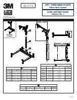
 See Figure 9 for reference. Pin Positions (PP) are listed 1 - 4. 

The Pin Positions regulate the Top Pulley (A4) and Bottom Pulley (A3) offsets. The first table within Figure 9 displays the 

maximum offset (Max) and minimum offset (Min) for each pulley in all four Pin Positions. Maximum offset is determined 

when the Adjustable Gusset is fully collapsed, with no visible threads. Minimum offset is determined when the Adjustable 

Gusset is fully extended. Once the Pin Position is set, the second table within Figure 9 should be consulted for the 

maximum load of each attachment point.


;

For use of the A1 attachment point, the distance of attachment from the Mast (Y) must be no greater than 15.0 in. 

(38.0 cm). 

Adjust the Davit base for the Davit mast:

 See Figure 10 for reference. Once the operating offset of the Davit Mast has 

been determined, the Davit Base should be adjusted to match its requirements. The Base Pin Position (BPP) of each Leg 

Assembly should be matched with the Pin Position of the Davit Mast. For example, a Pin Position of 4 on the Davit Mast 

should be matched with a Base Pin Position of 4 on the Davit Base.


;

After the Davit Base has been adjusted, verify that the Davit Base is level again with use of the Level Indicator. If 

necessary, make height adjustments of the Adjustable Feet.

5.0 INSPECTION

5.1 

INSPECTION FrEQUENCy:

 The Variable Davit System must be inspected at the intervals defined in Section 1. 

Inspection procedures are described in the 

‘Inspection and Maintenance Log’  in Table 2. 

Inspect all other components of 

the Fall Protection or Rescue System per the frequencies and procedures defined in the manufacturer’s instructions.


;

In addition to the annual inspection and inspection before each use, the Variable Davit System should be inspected 

at least once each week.

5.2 DEFECTS:

 If inspection reveals an unsafe or defective condition, remove the Variable Davit System from service 

immediately, clearly mark the system “DO NOT USE”, and destroy it or contact 3M regarding replacement. Do not attempt 

to repair the Fall Arrest System.

5.3 

PrODUCT LIFE:

 The functional life of the Variable Davit System is determined by work conditions and maintenance. As 

long as the product passes inspection criteria, it may remain in service.

6.0  MAINTENANCE, SERVICING, STORAGE

6.1 CLEANING:

 Periodically clean the metal components of the Variable Davit System with a soft brush, warm water, and a 

mild soap solution. Ensure parts are thoroughly rinsed with clean water.

6.2 SErVICE:

 Only 3M or parties authorized in writing by 3M may make repairs to this equipment. If the 

Variable Davit System has been subject to fall force or if inspection reveals an unsafe or defective condition, remove 

the system from service immediately, clearly mark the system “DO NOT USE”, and destroy it or contact 3M regarding 

replacement.


;

Only 3M or parties authorized in writing by 3M may make repairs to this equipment.

6.3 

STOrAGE AND TrANSPOrT:

 When not in use, store and transport the Variable Davit System and associated fall 

protection equipment in a cool, dry, clean environment out of direct sunlight. Avoid areas where chemical vapors may 

exist. Thoroughly inspect components after extended storage.

7.0 LABELS

Figures 11 and 12 illustrate labels present on the Variable Davit System. Figure 11 illustrates label locations and Figure 12 

displays the associated labels. Labels must be replaced if they are not present and fully legible. Information provided on each 

label is as follows:

1

A) Serial Number  B) Manufactured (Year/Month)  C) Lot Number  D) Model Number  E) Length (ft.)

2

A) Warning: Available Mast Offsets (Davit Mast)

3

A) Warning: Max working load 450 lb. (205 kg); Average Arresting Force 900 lbf (4.0 kN)

4

A) Warning: Read all instructions.

5

A) Warning: Available Mast Offsets (Davit Base)

6

Directional Indicator

7

Directional Indicator

8

A) Rated to ANSI Z359.1 requirements.  B) 5,000 lbf (22 kN) Maximum Arresting Force

Summary of Contents for DBI SALA Variable Davit

Page 1: ...3 0 in 7 6 cm 24 1 lb 10 9 kg A D E lbs kg 8518001 13 3 in 28 8 in 33 4 cm 73 2 cm 40 7 in 55 3 in 103 4 cm 140 5 cm 26 1 lb 11 8 kg 8518382 13 3 in 28 8 in 33 4 cm 73 2 cm 73 7 in 88 3 in 187 2 cm 22...

Page 2: ...2 2 A C B F G M J I K L H A D E C B N 3 4 B C FC C B A FC...

Page 3: ...3 5 6 A B C D E F G A B C 7 G E F D K K I B O J H D N M M L L M M 1 2...

Page 4: ...4 O S R P Q U T O S V 8 8518382 8518005 8518509 8518002 8518005 8518001 8518382 8518383 8518384 8518509 8518002 8518003 8518004 x 3 1 2...

Page 5: ...cm Max 18 5 in 47 0 cm 21 0 in 53 3 cm 25 0 in 63 5 cm 28 5 in 72 4 cm A PP1 PP2 PP3 PP4 A1 5 000 lbf 22 2 kN 5 000 lbf 22 2 kN 5 000 lbf 22 2 kN 5 000 lbf 22 2 kN A2 3 600 lbf 16 0 kN 3 000 lbf 13 0...

Page 6: ...a safety factor of 2 1 System rating is that of the lowest rated system component Cette composant est con u pour une charge de travail de 450 lb 205 kg Des dispositifs r tractables ou amortisseurs do...

Page 7: ...fully assembled adjusted and installed Do not adjust the system while a user is attached Only connect fall protection subsystems to the designated anchorage connection point on the device Prior to dr...

Page 8: ...Specifications Capacity 1 Person with a combined weight clothing tools etc of no more than 450 lb 205 kg Anchorage See Section 2 1 for more on anchorage strength requirements for use with the system...

Page 9: ...g Lanyard 900 lbf 4 kN PFAS with Self Retracting Device 900 lbf 4 kN 2 3 FALL PATH AND SRD LOCKING SPEED A clear path is required to assure positive locking of an SRD Situations which do not allow for...

Page 10: ...ooks and carabiners are required by ANSI Z359 and OSHA 2 9 MAKING CONNECTIONS Snap hooks and carabiners used with this equipment must be self locking Ensure all connections are compatible in size shap...

Page 11: ...rates installation of the Davit Base To install the Davit Base 1 To get started place each component of the Variable Davit System on the ground before you as seen in Figure 7 1 The Davit Arm B Davit M...

Page 12: ...intenance Log in Table 2 Inspect all other components of the Fall Protection or Rescue System per the frequencies and procedures defined in the manufacturer s instructions In addition to the annual in...

Page 13: ...t winches Self Retracting Devices SRDs etc that are used with the system should be inspected per the manufacturer s instructions Serial Number s Date Purchased Model Number Date of First Use Correctiv...

Page 14: ...positionn enti rement assembl ajust et install N ajustez pas le syst me lorsqu un utilisateur y est attach Ne connectez que les sous syst mes de protection antichute au point de connexion d ancrage d...

Page 15: ...syst me Capacit Une personne dont le poids combin avec v tements outils etc ne d passe pas 205 kg 450 lb Ancrage Voir la section 2 1 pour plus de renseignements sur les exigences de r sistance d ancr...

Page 16: ...ent comprendre un harnais de s curit complet avoir une distance de chute libre maximale de 1 8 m 6 pi et limiter la force d arr t moyenne aux valeurs suivantes Syst me antichute individuel avec longe...

Page 17: ...orme irr guli re celui ci risque d exercer une force sur le doigt du crochet ressort ou du mousqueton A Cette force peut entra ner l ouverture de la clavette B permettant ainsi au crochet ressort ou a...

Page 18: ...e bossoir m t de bossoir et bossoir Voir la figure 7 aux fins de r f rence Pour installer le syst me de bossoir variable INSTALLATION DE LA BASE DE BOSSOIR La figure 7 1 illustre l installation de la...

Page 19: ...et d entretien au tableau 2 Inspecter tous les autres composants du syst me de protection contre les chutes ou de sauvetage selon les fr quences et les proc dures d finies dans les directives du fabr...

Page 20: ...yst mes antichute individuels les treuils les dispositifs autor tractables etc suppl mentaires utilis s avec le syst me doivent tre inspect s conform ment aux directives du fabricant Num ro s de s rie...

Page 21: ...onado completamente ensamblado ajustado e instalado No ajuste el sistema mientras un usuario se encuentre conectado Solo conecte subsistemas de protecci n contra ca das al punto de conexi n de anclaje...

Page 22: ...ecificaciones del sistema Capacidad 1 persona con un peso combinado ropa herramientas etc de no m s de 450 lb 205 kg Anclaje Consulte la secci n 2 1 para obtener m s informaci n sobre los requisitos d...

Page 23: ...incorporar un arn s de cuerpo completo tener una ca da libre m xima permitida de 6 pies 1 8 m y limitar la fuerza de detenci n promedio a los siguientes valores PFAS con l neas de sujeci n con amortig...

Page 24: ...inferior o irregular podr a ocurrir que el elemento de conexi n aplique una fuerza a la compuerta del mosquet n A Esta fuerza puede hacer que la compuerta se abra B y permitir que el mosquet n se des...

Page 25: ...SCANTE La Figura 7 1 muestra la instalaci n de la base de pescante Para instalar la base de pescante 1 Para comenzar coloque cada componente del Sistema de pescante variable en el suelo y delante de u...

Page 26: ...l Registro de inspecci n y mantenimiento en la Tabla 2 Inspeccione todos los dem s componentes del Sistema de protecci n contra ca das o de rescate conforme las frecuencias y los procedimientos defini...

Page 27: ...El equipo adicional del Sistema personal de detenci n de ca das PFAS por sus siglas en ingl s los cabrestantes los dispositivos autorretr ctiles SRD por sus siglas en ingl s etc que se usan con el si...

Page 28: ......

Page 29: ...I S DE QUELQUE MANI RE AUX PRODUITS QUELLE QUE SOIT LA TH ORIE L GALE INVOQU E GARANT A GLOBAL DEL PRODUCTO REPARACIONES LIMITADAS Y LIMITACI N DE RESPONSABILIDAD GARANT A EL SIGUIENTE TEXTO SIRVE A M...

Page 30: ......

Page 31: ......

Page 32: ...ku Tokyo Phone 81 570 011 321 Fax 81 3 6409 5818 psd jp mmm com WEBSITE 3M com FallProtection I S O 9 0 0 1 FM534873 EU DECLARATION OF CONFORMITY 3M com FallProtection DOC U S PRODUCT WARRANTY LIMITE...

Reviews: