9
3.0 INSTALLATION AND USE
3.1
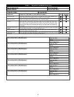
BEFORE EACH USE
of this equipment inspect it according to the
“Inspection and Maintenance Log” (Table 1)
.
3.2 PLAN
your system before use. Consider all factors that will affect your safety during use of this equipment. The following
list gives important points to consider when planning your system:
• Anchorage:
Select an anchorage capable of sustaining the Static Load requirements of the intended fall protection
application (see Section 1.1). The anchorage location should address Free Fall, Fall Clearance, Swing Fall, and
Environmental limitations described in Section 1.4.
• Sharp
Edges:
Avoid working where system components may be in contact with, or abrade against, unprotected
sharp edges.
• After A Fall:
Components which have been subjected to the forces of arresting a fall must be removed from service
and destroyed.
• Rescue:
The employer must have a rescue plan when using this equipment. The employer must have the ability to
perform a rescue quickly and safely.
• Rescue
Harness:
Rescue Harnesses are intended to be worn during normal work activities. Before using rescue
attachment elements for the
fi
rst time, the user should carry out a suspension test in safe conditions to ensure the
harness is sized and
fi
tted for optimal comfort during suspension.
3.3 ANCHORAGE
REQUIREMENTS:
The Riggersmate Hauling Kits should be attached to a suitable anchorage or anchorage
connector capable of supporting the required loads. As per AS/NZS 5532: 2013 the anchorage connector should be rated
to a minimum of 12kN for single person use and 18kN for 2 person use.
3.4 INSTALLATION
REQUIREMENTS:
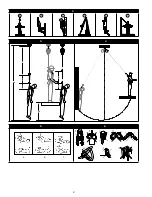
1. Attach the Hauling Kit to a suitable anchorage connector as per section 3.3, using the connector provided
on the head unit.
2. The travel assembly end of the device can then be attached to the load using the connector provided.
3.5 RAISING:
1. Raise a load by pulling the tail end of the rope.
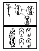
2. Whilst the load is being raised, the locking cam will engaged and disengaged once every revolution of the
top pulley, making a clicking sound.
3. Continue pulling the tail end of the rope until the load reaches the required position.
4. Slow release the tail end of the rope. If the rope tail tries to pull back through the device, raise the load
another 50mm to engage the locking cam.
5. The travel assembly should never be raise to interfere with the rope termination.
3.6 LOWERING:
1. To lower the load, pull on the tail end of the rope until the locking cam disengages.
2. Slowly allow the tail end of the rope be pulley back through the device by the raise load.
3. To stop lowering, pull on the tail end of the rope and raise the load 50mm to engage to locking cam.
3.7 MAKING
CONNECTIONS:
When using a hook to connect to an anchorage or when coupling components of the system
together, ensure roll-out cannot occur. Roll-out occurs when interference between the hook and mating connector causes
the hook gate to unintentionally open and release. Self-locking snap hooks and carabiners should be used to reduce the
possibility of roll-out. Do not use hooks or connectors that will not completely close over the attachment object. See
subsystem manufacturer’s instructions for more information on making connections.
3.8 OVER-SPEED
LOCK:
All Riggersmate Hauling Kits are equipped with an internal over-speed lock. If at any point during
operation the load becomes uncontrolled or the tail end of the rope released, this feature will automatically lock and
prevent the load from falling to the ground. If the over-speed lock is activated, follow the lowering procedure, section
3.6, to continue operation. As soon as possible after an over-speed lock the unit shall be inspected as per section 5 of this
manual. Do not continue to use this product after an over-speed lock unless completing a rescue.

