19
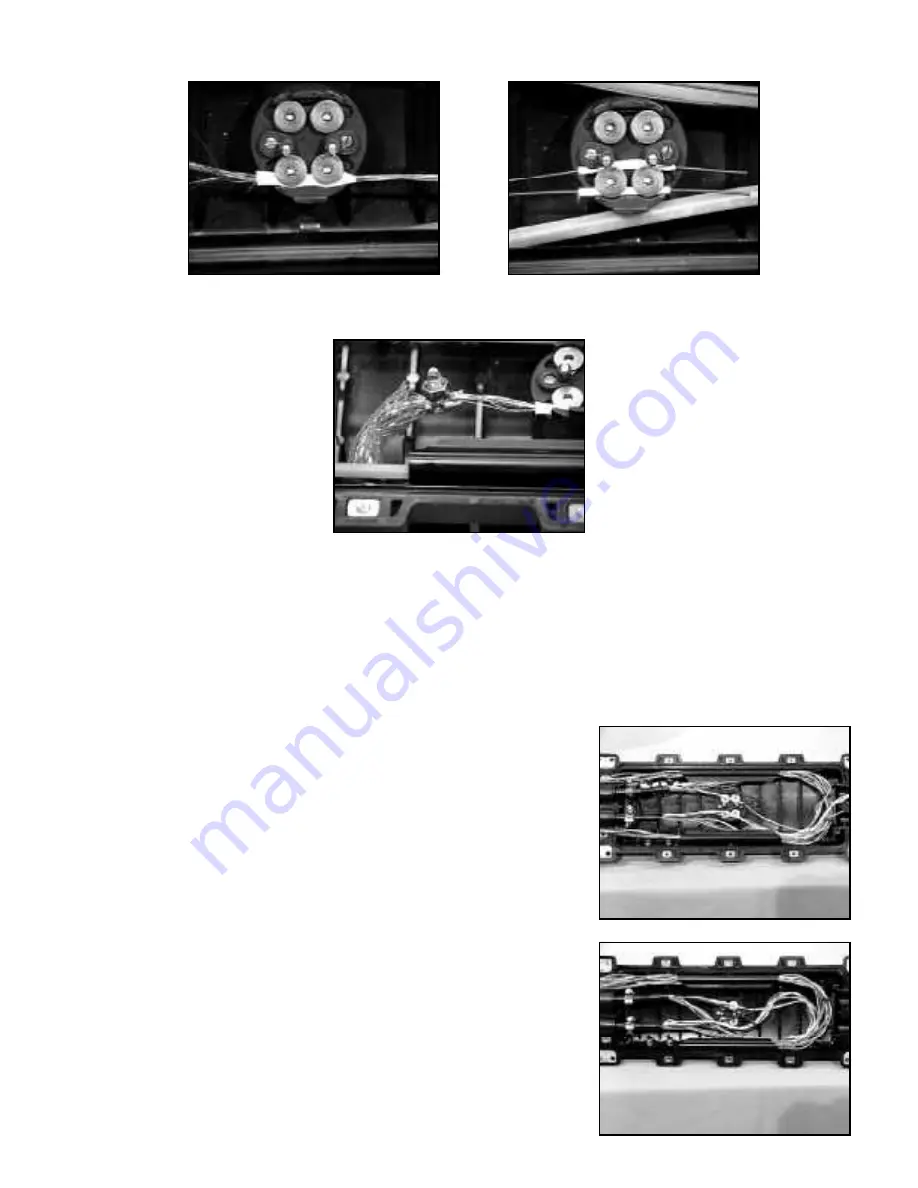
f. The crossply members go under both central retention screws along the outer edge. The LXE members
go under both sides of the two screws. Make sure the taped area is under the screws.
g. A split bolt clamp is required to join the crossply members to a number six or equivalent bond strap.
Wrap vinyl tape over the bolt connection to protect against sharp edges or pinch points. Attach external
ground stud.
11.0 Buffer Tube and Ribbon Cable Preparation
11.01 Unit splitter kits are required on all ribbon, unitube, or slotted core cable. Follow instructions supplied with
the unit splitter kits.
11.02 Gather all buffer tubes from "C.O. Cable" and install one small green cable tie approximately 36" (914 mm)
from sheath end. Install one small blue cable tie on the "Field Cable" buffer tubes or ribbon cable.
Note:
Spiral wrap or equivalent must be applied to unitube cable before applying cable tie.
11.03 Coil buffer tube, ribbon, unitube, or fibers bundles inside splice
case base. If using a splice tray that allows fiber entry at all four
corners or two corners in the same end, the last 3/4 loop will
allow tray movement for splicing away from splice case. Coils
should be full splice case base length and width and should be
under the cable and central member.
11.04 When using the 2524-FT Fibrlok splice trays, or other trays that
allow fiber entry from the same corner, the buffer tubes, ribbon,
unitube or slotted core fiber will need to route in the same
direction together. This is accomplished by having the fiber from
one cable pass in front of the central clamp and follow the route
of the other fiber. The 3M Fibrlok splice tray requires a
counterclockwise direction. Follow supplied instructions with
other splice trays to determine fiber route direction.


