background image

Figures

Figure 1.1.1: Solo System Context Diagram 

1

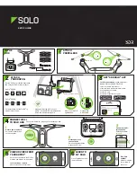
Figure 1.2.1: Solo Exterior Overview 

2

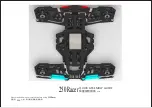
Figure 1.2.2: Solo Interior Overview 

3

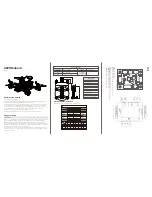
Figure 1.3.1: Controller Schematic Diagram 

4

Figure 1.4.1: Solo Operating Parameters & Specifications Table 

5

Figure 1.5.1: Solo Onboard Sensors Table 

6

Figure 1.6.1: Motor Schematic Diagram 

6

Figure 1.6.2: Solo Motor Order 

7

Figure 1.7.1: Solo Electrical System 

7

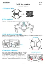
Figure 2.1.1: Solo Parts 

9

Figure 2.2.1: Charge Solo Battery 

10

Figure 2.2.2: Insert Solo Battery 

10

Figure 2.3.1: Charge Controller 

11

Figure 2.3.2: Power On Controller 

11

Figure 2.4.1: Attach Propellers 

12

Figure 2.5.1: Attach Camera 

13

Figure 2.5.2: Camera Configuration Process 

13

Figure 2.6.1: Connect to Solo Link 

14

Figure 2.6.2: Controller Preflight Update Prompt 

14

Figure 2.6.3: Solo App Update Process 

14

Figure 2.6.4: Controller Updating Display 

15

Figure 2.6.5: Controller Update Display 

15

Figure 2.6.6: Solo Update Displays 

15

Figure 2.6.7: Viewing Video on the App 

15

Figure 3.5.1: Controller Maximum Altitude Warning 

17

Figure 3.7.1: Low controller battery warning and return-home notifications 

18

Figure 3.7.2: Low flight battery warning and auto-land notifications 

18

Figure 3.10.1: Controller Waiting-for-GPS Prompt 

19

Figure 3.10.2: Controller GPS Lost Notification 

19

Figure 3.11.1: Controller Signal Lost Warnings With GPS 

20

Figure 3.11.2: Controller Signal Lost Warnings Without GPS 

20

Figure 4.2.1: Controller Start Motors Prompt 

21

Figure 4.2.2: Controller Auto-Takeoff Prompt 

22

Figure 4.3.1: Return Home Behavior 

22

Figure 4.4.1: Controller In-Flight Data Display 

23

Figure 4.5.1: Controller Left Joystick 

24

Figure 4.5.2: Throttle Joystick Behaviors 

24

Figure 4.5.3: Yaw Joystick Behavior 

25

Figure 4.5.4: Controller Right Joystick Controls 

25

Figure 4.5.5: Pitch Joystick Controls 

26

Figure 4.5.6: Roll Joystick Controls 

26

Figure 5.1.1: Leg Replacement Process 1 

28

Figure 5.1.2: Leg Replacement Process 2 

28

Figure 5.1.3: Leg Replacement Process 3 

29

Figure 5.2.1: Motor Pod Replacement Process 1 

29

Figure 5.2.2: Motor Pod Replacement Process 2 

30

Figure 5.2.3: Motor Pod Replacement Process 3 

30

Figure 5.2.4: Motor Pod Replacement Process 4 

30

Figure 5.2.5: Motor Pod Replacement Process 5 

31

Figure 5.3.1: Solo Pair Button 

31

Figure 5.3.2: Controller Pairing Process 

31

Summary of Contents for Solo

Page 1: ...Operation Manual...

Page 2: ...l 1 858 225 1414 direct 1 855 982 2898 toll free in the US and Canada Support line hours Mon Fri 8 am to 5 pm PST Sat 9 am to 3 pm PST 3D Robotics 3DR 1608 4th Street Suite 410 Berkeley CA 94710 Tel 1...

Page 3: ...Awareness 16 3 3 Propellers 16 3 4 Home Position 16 3 5 Altitude Safety Fence 17 3 6 Emergency Procedures 17 3 7 Power Management 17 3 8 Flight Battery 18 3 9 Controller 18 3 10 GPS Management 19 3 11...

Page 4: ...ntroller battery warning and return home notifications 18 Figure 3 7 2 Low flight battery warning and auto land notifications 18 Figure 3 10 1 Controller Waiting for GPS Prompt 19 Figure 3 10 2 Contro...

Page 5: ...ns in flight while sending real time telemetry and video output and receiving control inputs over the 3DR Link secure WiFi network Solo is optimized for aerial imagery using a GoPro HERO camera Contro...

Page 6: ...he HDMI cable connects to the GoPro to output video and charge the camera during flight Figure 1 2 1 Solo Exterior Overview Solo Mainboard The Solo mainboard connects all components onboard Solo It ac...

Page 7: ...tion of the motors to achieve the correct flight speeds 3DR Solo Link The 3DR Solo Link module manages communication between Solo and the controller on the 3DR Link secure WiFi network 3DR Solo Link r...

Page 8: ...lets you control Solo s main flight functions starting motors auto takeoff auto land and activating manual flight Return Home The return home button allows you to end your flight automatically at any...

Page 9: ...Pixhawk 2 runs an ARM Cortex M4 STM32F427 processor with 2 MB of flash memory and 256 KB of RAM Combined with an array of CAN I2C SPI PWM and UART interfaces Pixhawk 2 uses a suite of onboard sensors...

Page 10: ...k 2 FMU Gyroscope InvenSense MPU6000 Motion Pixhawk 2 FMU Magnetometer Honeywell HMC 5983 Cardinal direction Pixhawk 2 FMU Barometer Measurement Specialties MS5611 Altitude Pixhawk 2 Stabilized IMU Ac...

Page 11: ...telemetry output to the operator to provide data for in flight power management and battery failsafe Mainboard The Solo mainboard passes regulated voltage to the computing components onboard Solo Pix...

Page 12: ...uts to Solo over the 3DR Link network The redirection of controls from the app is due to the improved range of the controller s antennas Solo receives the controls through 3DR Solo Link and transfers...

Page 13: ...e level of the battery is indicated by the lights below the power button Press the power button once to display the current power level The Solo battery ships with approximately 50 charge so charge fu...

Page 14: ...ion and you will hear the startup tone Only power Solo using the designated 3DR Solo Smart Battery using a different battery can permanently damage Solo Figure 2 2 2 Insert Solo Battery Charge indicat...

Page 15: ...r batteries If the battery s connector comes into contact with a metal object it can short circuit the battery and cause a fire Charging Only charge the controller using the designated controller char...

Page 16: ...e motor shaft and attach the black top propellers to the motors with the black dots Make sure to remove the paper labels from the motors before attaching the propellers Silver top propellers tighten c...

Page 17: ...orientation and medium field of view Setting the field of view to medium ensures that you won t see the propellers in the frame Figure 2 5 2 Camera Configuration Process Make sure that the Wi Fi on yo...

Page 18: ...o continue Figure 2 6 1 Connect to Solo Link Update Before your first flight perform the required first flight update for Solo and the controller using the app The controller will prompt you for the u...

Page 19: ...e the update Figure 2 6 5 Controller Update Display After pressing A Solo will update The controller will display waiting for Solo and Solo updating Figure 2 6 6 while the update is in progress When t...

Page 20: ...as rain high winds snow or fog Environmental factors and GPS irregularities can cause instability in flight and this can affect Solo s performance or cause an in flight failure 3 3 Propellers When pr...

Page 21: ...cle or to re orient Solo for navigation Regain Manual Control During Smart Shots and other autonomous behaviors keep the controller easily accessible and be prepared to regain manual control at any ti...

Page 22: ...normal smell leakage or other unexpected behavior do not use the battery These can be signs of serious damage that can cause the battery to catch fire or explode In this case do not use the battery ag...

Page 23: ...res or direct sunlight 3 10 GPS Management Solo requires an active GPS signal for advanced automated functions and Smart Shots After powering on Solo will wait to acquire a strong GPS lock The followi...

Page 24: ...flight Solo will automatically return home if it has GPS lock If the signal is recovered the user will be prompted to re take control and cancel the return home command Figure 3 11 1 Controller Signa...

Reviews: