3Disc Fire CR dental Service Manual Download Page 52


51


PMT gain and ADC offset verification/adjustment 

Whenever parts that have influence on the gain and offset are replaced it is important to verify, and if 
necessary adjust the PMT gain and ADC offset to ensure that the image quality is not lowered.  
 
To properly verify the PMT gain and ADC offset you will need the following items;  


 QuantorDent(Vet) or similar acquisition software installed on a PC. 


Size 4C dental IP. 


Dosimeter to measure absolute dose. 


X-ray generator. 


ADC offset verification and adjustment 

1.


Connect the unit to both a PC and power outlet. 

2.


Switch the unit on. 

3.


Enter the 

calibration menu

 as described in the user manual for your software. 
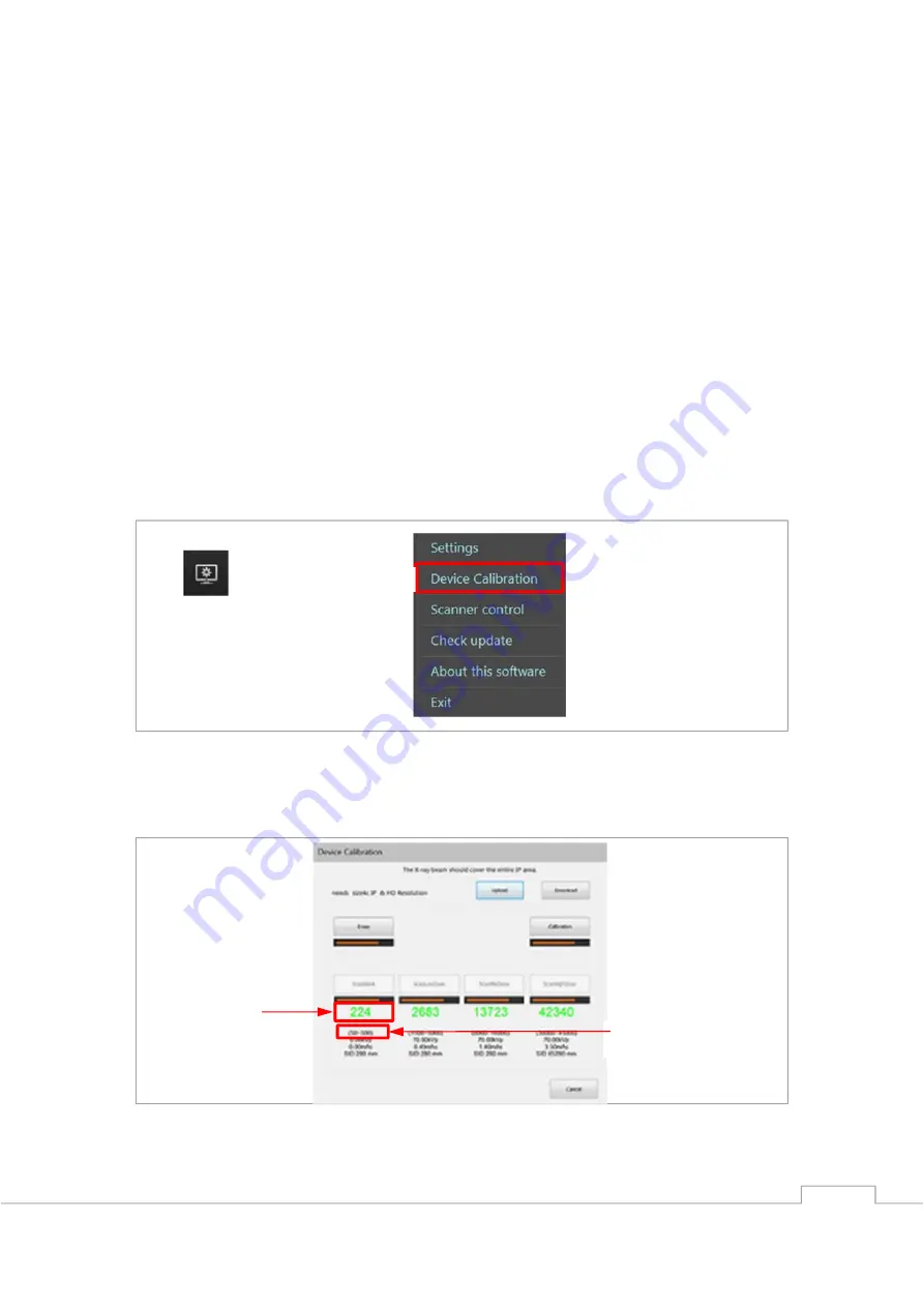
4.


For Quantor users use the options icon (

1

) in the top right hand corner and select “

Device 

calibration

” (

2

). 


5.


Position the size 4C IP on the tray and close it to erase the IP. 

6.


Remove the IP from the tray and reposition it on the tray. 

7.


Scan the IP using the blank calibration position. 

8.


Compare the readout value to the tolerance for the blank calibration. 


2


Blank scan tolerance. 

Blank scan 

readout value. 

Summary of Contents for Fire CR dental

Page 1: ...Service Manual Hardware revisions AH and later ...

Page 2: ...1 ...

Page 3: ...ifications which must be met by 3D Imaging Simulations Corp All information contained herein is intended for guidance purposes only and characteristics of the products and services described in this publication can be changed at any time without notice Products and services may not be available in your local area Please contact your local sales representative for availability information 3D Imagin...

Page 4: ...raser 19 Replacing the right PSD sensor 20 Replacing the PMT assembly 21 Replacing the power board 23 Replacing the main board 24 Replacing the BLDC driver board 27 Replacing the mains power switch 28 Replacing the SD memory card 30 Replacing the RFID board 31 Replacing the tray assembly 34 Replacing the bottom board 36 Replacing the stage base assembly 39 Replacing the drive belt 45 Replacing the...

Page 5: ...centre part of the serial number contains two decimals and 4 alphanumerical characters the last two identifies the hardware revision Please ensure these are AH or later e g FR 11 00DHAH XXXXXX on some units the serial has been changed to a UDI the hardware revision for these can be verified like shown in the following example 1 08809466040214 11 160502 10 FR1100AH 21 XXXXXX ...

Page 6: ...lacement Disassembly 1 Set the reader into sleep mode by pressing on the half moon symbol on the display 2 Switch off the reader on the back and disconnect all cables Ethernet Power switch Off On USB socket Power inlet ...

Page 7: ...move the rear cover 4 Push the door inwards and upwards to gain a decent handhold on the inside of the front cover 1 then pull outwards and upwards to remove the front cover from the rest of the unit 2 5 Turn the front cover over to gain access to the cables 1 2 ...

Page 8: ...ribbon cable and disconnect the ribbon cable 1 and motor power cable 2 from the TFT LCD display driver board 7 Put the reader on the side being careful not to damage it and remove the 6 screws using a Philips 2 screwdriver 1 2 ...

Page 9: ...8 8 Set the reader back upright and carefully lift the top cover off ...

Page 10: ...9 9 Remove the 4 screws fastening the inner chassis using a 2 5 mm hex key and lift it off ...

Page 11: ...tall in reverse order Replacing the top cover 1 Follow step 1 through 8 of Disassembly 2 Turn the cover over and release the locks fastening the top cover onto the side cover 3 Replace the top cover and install in reverse order Replacing the side cover 1 Follow step 1 through 8 of Disassembly 2 Turn the cover over and release the locks fastening the top cover onto the side cover 3 Replace the side...

Page 12: ...emove the 6 screws using a 2 5mm hex key and remove the bottom cover 3 Replace the bottom cover and install in reverse order Replacing the rear cover 1 Follow step 1 through 3 of Disassembly 2 Replace the rear cover and install in reverse order Replacing the front board 1 Follow step 1 through 9 of Disassembly 2 Unlock 1 and disconnect 2 the ribbon cables from the front board 3 Unplug the connecto...

Page 13: ...12 4 Remove the 3 screws using a 2 5 mm hex key 5 Replace the front board and install in reverse order ...

Page 14: ...PSD sensor 1 Follow step 1 through 9 of Disassembly 2 Remove the 2 screws using a 2 5 mm hex key 3 Cut the cable tie and disconnect the PSD sensor from the front board PCB 4 Replace the left PSD and install in reverse order ...

Page 15: ... Disassembly 2 Disconnect the BLDC motor 1 and laser 2 from the front board 3 Remove the 3 screws using a 2 5 mm hex key letting the front board hang loose 4 Remove the 4 screws using a 2 5 mm hex key 5 Replace the laser module and install in reverse order 1 2 ...

Page 16: ...hrough 9 of Disassembly 2 Disconnect J1 and J4 from the bottom board 3 Unlock 1 and disconnect 2 the ribbon cable from the front board 4 Put the scanner onto its side and remove the 6 screws using a 2 5mm hex key and remove the bottom cover J1 J4 1 2 ...

Page 17: ...ews fastening the left PSD using a 2 5 mm hex key 6 Rotate the unit to the other side and remove the 2 screws fastening the right PSD using a 2 5 mm hex key 7 Cut the cable tie and disconnect the eraser from the front board ...

Page 18: ...y 9 Carefully lift the optics assembly out of the unit 10 Remove the 4 screws from the bracket using a 2 5 mm hex key 11 Remove the 2 screws fastening the eraser using a Philips 1 screwdriver 12 Remove the eraser 1 while guiding the wires through the eraser cover 2 ...

Page 19: ...18 13 Replace the optics bracket and install in reverse order 1 2 ...

Page 20: ... Cut the cable tie and disconnect the eraser from the front board 14 Remove the 2 screws fastening the eraser using a Philips 1 screwdriver 15 Remove the eraser 1 while guiding the wires through the eraser cover 2 3 Replace the eraser and install in reverse order 1 2 ...

Page 21: ... PSD sensor 1 Follow step 1 through 9 of Disassembly 2 Disconnect the PSD sensor from the front board 3 Remove the 2 screws fastening the right PSD using a 2 5 mm hex key 4 Replace the PSD sensor and install in reverse order ...

Page 22: ...remove the 6 screws using a 2 5mm hex key and remove the bottom cover 3 Disconnect the BNC 1 and HV 2 connectors from the back of the main board 4 Rotate the unit to access the opposite side and remove the 2 screws fastening the bracket using a Philips 1 screwdriver Reuse the bracket during installation 1 2 ...

Page 23: ...ove the 4 screws on the bottom of the unit using a 3 mm hex key 6 Replace the PMT assembly and install in reverse order reusing the metal bracket 7 Continue onto PMT gain and ADC offset verification adjustment ...

Page 24: ...tor 1 and mains power switch 2 from the power board 3 Remove the tape from the power board 4 Remove the 4 screws fastening the power board using 2 5 mm hex key 5 Remove the power board by pulling it out of the connector on the main board 6 Replace the power board and install in reverse order 1 2 ...

Page 25: ... 1 Follow step 1 through 9 of Disassembly 2 Disconnect the step motor 1 and mains power switch 2 from the power board 3 Remove the tape from the power board 4 Remove the 4 screws fastening the power board using 2 5 mm hex key 1 2 ...

Page 26: ...ain board 6 Rotate the unit to gain access to the other side and disconnect the BNC 1 and HV 2 connectors from the back of the main board 7 Disconnect J5 and J7 from the back of the main board 8 Unlock 1 and disconnect 2 the ribbon cable from the front board 1 2 J5 J7 1 2 ...

Page 27: ...om the electronics bracket 11 Release the SD card by pressing on it 1 until you hear a soft click then pulling it out of the card holder 2 12 Replace the main board and install in reverse order 13 Update the firmware in the unit as described in the Updating the firmware after parts replacement section 1 2 ...

Page 28: ...p 1 through 9 of Disassembly 2 Disconnect J2 and J3 from the BLDC driver board 3 Remove the 4 screws using a 2 5 mm hex key 4 Replace the BLDC driver board and ensure the DIP switches are set to 0011 off off on on and install in reverse order J2 J3 ...

Page 29: ...itch 1 Follow step 1 through 9 of Disassembly 2 Remove the wires from the mains power switch by pulling the connectors off 3 Press the 2 locks inwards and remove the mains power switch out of the rear of the electronics bracket 1 1 2 ...

Page 30: ...29 4 Replace the mains power switch and install in reverse order ensuring the orientation of the mains power switch is as shown ...

Page 31: ...l you hear a soft click 3 Replace the SD card and install in reverse order ensuring the orientation of the SD is as shown 4 Update the firmware in the unit as described in the Updating the firmware after parts replacement section 5 Continue onto PMT gain and ADC offset adjustment 6 Continue onto Scanner calibration ...

Page 32: ...piano wire tray assembly 1 Follow step 1 through 9 of Disassembly 2 Move the tray assembly to the front of the unit by bushing on the back of the tray assembly until the IP tray is released 3 Remove the screws fastening the spring brackets to the tray using a 2 5 mm hex key There is one located on either side of the tray assembly ...

Page 33: ...FC cable is fastened with an adhesive and may be disconnected if the tray is on pulled too hard 5 Remove the screw fastening the micro switch using a PH0 screwdriver 6 Remove the screw fastening the tray onto the mounting bracket using a 2 5 mm hex key 7 Remove the 2 screws on either side of the tray using a PH1 screwdriver ...

Page 34: ...connect 2 the flexible FFC cable 9 Replace the RFID board and install in reverse order taking care that the 2 screws fastening the tray are not tightened too much as this would restrict the movement of the tray assembly 1 2 ...

Page 35: ...ep 1 through 9 of Disassembly 2 Unlock 1 and disconnect 2 the flexible FFC cable from the bottom board using a pair of tweezers as the connector is positioned behind the bracket 3 Rotate the unit to gain access to the other side and move the tray assembly to the shown position and remove the 2 screws fastening the clamp using a 1 5 mm hex key Then remove the clamp 1 2 ...

Page 36: ...move the bearing 6 Remove the screw for the bottom board PCB frame using a 2 5 mm hex key as the frame acts as an end stop for the tray assembly 7 Lift the frame out of the way and slide the tray assembly off the rail bear in mind the ribbon cable is fastened with an adhesive 8 Replace the tray assembly and install in reverse order noting the orientation of the flexible FFC cable ...

Page 37: ...y 2 Unlock 1 and disconnect 2 the flexible FFC cable from the bottom board using a pair of tweezers as the connector is positioned behind the bracket 8 Disconnect J1 and J4 from the bottom board 3 Remove the 2 screws from the bottom board using a 2 5 mm hex key 1 2 J1 J4 ...

Page 38: ...37 4 Remove the screw fastening the bottom board frame using a 2 5 mm hex key 5 Lift the frame up and to the side to allow the bottom board to come out 6 Slide the bottom board out ...

Page 39: ...38 7 Replace the bottom board and install in reverse order ...

Page 40: ...se assembly 1 Follow step 1 through 9 of Disassembly 2 Disconnect the stepper motor from the power board 9 Disconnect J1 and J4 from the bottom board 4 Remove the 6 screws using a 2 5mm hex key and remove the bottom cover J1 J4 ...

Page 41: ...ove the 12 screws on the bottom using a 3 mm hex key 4 Carefully remove the stage base assembly from the remaining assemblies 5 Remove the 4 screws from the stepper motor mounting bracket using a 2 5 mm hex key ...

Page 42: ...pper motor shaft using a 1 5 mm hex key You may have to rotate the step motor to gain access to the screws 7 Lift the stepper motor up and out of the socket 8 Remove the 2 screws fastening the clamp using a 1 5 mm hex key and remove the clamp ...

Page 43: ...the motor base 10 Remove the drive belt 11 Rotate the unit to gain access to the opposite side and unlock 1 and disconnect 2 the ribbon cable from the bottom board 12 Remove the screws from the bottom board using a 2 5 mm hex key and remove the bottom board 1 2 ...

Page 44: ...tom board frame using a 2 5 mm hex key 14 Remove the screw from the ejector guide using a 2 5 mm hex key then remove the ejector guide 15 Remove the 4 screws from the drive belt bearing using a 2 5 mm hex key and remove the drive belt bearing ...

Page 45: ...44 16 Lift the frame up and to the side to allow the tray assembly to slide off the rail 17 Replace the stage base assembly and install in reverse order ...

Page 46: ...mbly 2 Remove the 4 screws from the stepper motor mount using a 2 5 mm hex key 3 Loosen the 2 socket screws from the step motor drive shaft using a 1 5 mm hex key you may have to rotate the step motor to gain access to the screws 4 Lift the step motor out of the way ...

Page 47: ...2 screws fastening the clamp using a 1 5 mm hex key Then remove the clamp 6 Remove the 3 screws from the motor base using a 2 5 mm hex key 7 Remove and replace the drive belt install the new drive belt in reverse order ...

Page 48: ... if the unit has a ws10 mm stepper motor please follow the steps in the upgrade manual for stepper motor and power board 1 Follow step 1 through 9 of Disassembly 2 Disconnect the stepper motor power cable from the motor 3 Remove the 4 screws from the stepper motor mount using a 2 5 mm hex key ...

Page 49: ...ft using a 1 5 mm hex key you may have to rotate the step motor to gain access to the screws 5 Lift the stepper motor up 6 Remove the 4 screws fastening the motor mount to the stepper motor and reuse the motor mount during installation 7 Install in reverse order ...

Page 50: ...s you need to set the firmware updater into factory mode This is done by creating an empty text txt named factory_mode txt This file should be located in the same folder as the firmware updater for it to activate the extended functionality Double click the DentalCR_SystemUpdater exe file to start the firmware update application The version of the updater can be seen in the second line in the log w...

Page 51: ...th a drive belt AC ws 10mm stepper motor with drive belt AD sst 10mm stepper motor with drive belt AE ws 10mm AG stepper motor with drive belt AF ws 10mm AG stepper motor with drive belt AG ws 10mm AG stepper motor with drive belt AH ws 10mm AH stepper motor with drive belt AJ SAEHAN stepper motor with drive belt Main board Select the version of main board that is currently installed in the unit T...

Page 52: ...measure absolute dose X ray generator ADC offset verification and adjustment 1 Connect the unit to both a PC and power outlet 2 Switch the unit on 3 Enter the calibration menu as described in the user manual for your software 4 For Quantor users use the options icon 1 in the top right hand corner and select Device calibration 2 5 Position the size 4C IP on the tray and close it to erase the IP 6 R...

Page 53: ...ust the value next to the label ADC offset Increasing the value will increase the ADC offset level resulting in a lower readout value on the next scan Decreasing the value will decrease the ADC offset level resulting in a higher readout value on the next scan Once the value has been altered click on the button labelled Save Params A dialogue will appear asking that you switch the unit off close th...

Page 54: ...53 9 Repeat the procedure until the readout value is within the blank scan calibration tolerance then continue onto PMT gain verification and adjustment Save Params ...

Page 55: ...he tolerance for the high dose calibration If the readout value is within the tolerances for the high dose calibration continue onto Scanner calibration If the readout value is outside the high dose calibration tolerances open the scanner control panel and check the box next to the Edit Params label High dose tolerance Low dose scan readout value Edit parameters checkbox ...

Page 56: ...ulting in a lower readout value on the next scan Once the value has been altered click on the button labeled Save Params A dialog will appear asking you to switch the unit off close the software switch the unit on and reopen the software 3 Repeat the procedure until the readout value is within the high dose calibration tolerance then continue onto Scanner calibration PMT Gain Save Params ...

Page 57: ...referably a dosimeter Before calibrating ensure that the unit is scanning with HD resolution by looking in the top of the LCD display on the unit If the unit is scanning with SD resolution enter the settings menu by pressing on the cog wheel on the LCD display of the unit Select the Resolution field ...

Page 58: ... display to go back one step Press the back button again to exit the settings menu 1 Enter the calibration menu as described in the user manual for your software For Quantor users use the options icon 1 in the top right hand corner and select Device calibration 2 1 2 1 2 ...

Page 59: ...58 2 Follow the on screen guide to calibrate the unit using the following dose for each step Blank 0µGy Low dose 70µGy Middose 325µGy High dose 1100µGy 3 Select Calibration to complete the calibration ...

Page 60: ...tion is done a pop up window will confirm that it was successful Select OK to continue 5 Upload the new calibration data to the unit by selecting OK 6 Select Yes to use the new calibration 7 Select OK to start the transfer ...

Page 61: ...60 LCD calibration 1 Go to the settings menu using the cog wheel on the LCD display of the unit 2 Enter the network setting menu 3 Select the IP address field ...

Page 62: ...nd enter 5 dots 2 The IP address will be restored automatically when the calibration is finished 5 Select the check mark on the display of the unit to boot the unit in LCD calibration mode 6 Press in the center of the 5 crosshairs to calibrate the display 7 The scanner is now ready for use 1 2 ...

Page 63: ...62 ...

Page 64: ...eon gil Yuseong Gu Daejeon Korea Tel 82 42 931 2100 Fax 82 42 931 2299 E mail info 3DISCimaging com 3DISC Americas Inc 22560 Glenn Drive Suite 116 Sterling VA 20164 United States Tel 1 800 570 0363 3DISC Europe ApS Gydevang 39 41 3450 Alleroed Denmark Tel 45 88 276 650 ...

Reviews: