3D SYSTEMS, INC.
75-D059 REV_A
19
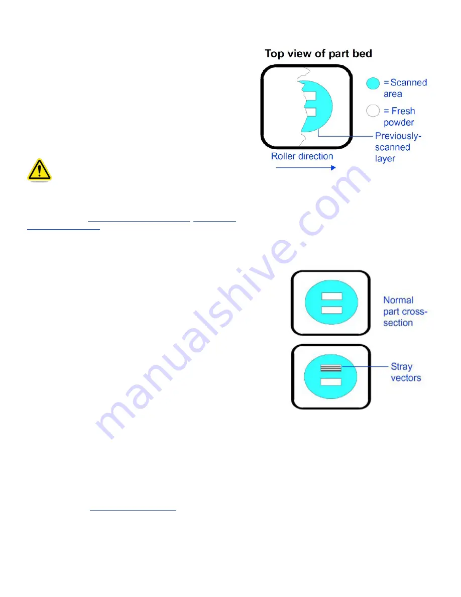
SHORT FEEDS
Description: The roller does not deliver enough material to cover the
previous layer .
Theory of Cause
: Short feeds can occur when the feed amount is
too short; the part cross-section changes from small to large.
Visual Signs
: Part bed not completely covered after a layer is
spread . Part bed cracking may also appear .
Consequences
: The part will usually be weak, may delaminate
at layers where short feeds occurred, and may have surface
imperfections .
Corrective Action: Increase the Feed Amount parameters in the Print
Parameters Profile or use the Prime Cycle button.
Caution! Exercise care when varying the Feed Amount
parameters. The feed material during a print is
considerably cooler than the material in the print
bed. Using a feed that is too large can cause excessive
cooling of the part as the material is delivered, which
will lead to curl during printing.
You also may want to use the Prime Cycle button to cover the part .
Related Problems
“Melting, Print Bed” on page 17
STRAY VECTORS
Description:
A line occurs between two fill areas where it should
not be .
Theory of Cause:
The STL file is incorrect. The vertices of the facet
do not meet . This is not material related .
Visual Signs:
The laser scans an area in the cross-section that it
should not scan . This usually results in one or more lines connecting
the fill areas.
Consequences:
Stray vectors make it more difficult to clean and
break out parts .
Corrective Action:
Prior to beginning the print, check the STL file
for stray vectors using the Preview tab in Build Setup . Rotate the
orientation of the part slightly . Preview the part again . Verify the
original CAD file.
If the original CAD file is correct
, the STL file has probably been
corrupted and you must make a new one . Repeat the process to
save the file into the STL format: copy the new file to the SLS system
computer, set up a build packet with the new file, and preview it
again . If the problem recurs, contact 3D Systems customer support .
If the original CAD file is incorrect
, make the necessary changes to the
CAD file, save the file into the STL file format, and copy the new file
onto the SLS system computer. With the new file, set up a new build
packet and try printing the part again .
If the stray vectors are not too severe, file or cut them off. If the
problem is too severe, you may need to terminate the print; trying
to remove severe stray vectors from the part during breakout may
cause the part to break .
Related Problems:


