


Overview
453
3 switch in the leaf network (Switch B in the figure). The Layer 3 switch will then
forward IGMP join or IGMP leave messages sent by the connected hosts. After the
configuration of IGMP Proxy, the leaf switch is no longer a PIM neighbor but a
host for the external network. Only when the Layer 3 switch has directly
connected members, can it receive the multicast data of corresponding groups.
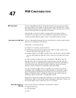
Figure 111
Diagram for IGMP Proxy
Figure 111 is an IGMP Proxy diagram for a leaf network.
Configure Switch B as follows:
■
Enable multicast routing on VLAN interface 1 and VLAN interface 2, and then
configure the PIM protocol on it. And configure the IGMP protocol on
VLAN-interface 1 at the same time.
■
On VLAN interface 2, configure VLAN interface 1 as the outbound IGMP Proxy
interface to external networks. You must enable the IGMP protocol on the
interface first, and then configure the igmp proxy command.
Configure Switch A as follows:
■
Enable multicast routing and configure the IGMP protocol on VLAN interface 1.
■
Configure the pim neighbor-policy command to filter PIM neighbors in the
network segment 33.33.33.0/24. That is, Switch A does not consider Switch B
as its PIM neighbor.
In this case, when Switch B of leaf network receives from VLAN interface 2 an
IGMP join or IGMP leave message sent by the host, it will change the source
address of the IGMP information to the address of VLAN interface 1: 33.33.33.2
and send the information to VLAN interface 1 of Switch A. For Switch A, this
works as if there is a host directly connected to VLAN interface 1.
Similarly, when Switch B receives the IGMP general group or group-specific query
message from the Layer 3 Switch A, it will also change the source address of the
query message to the IP address of VLAN interface 2: 22.22.22.1 and send the
message from VLAN interface 2.
In Figure 111, VLAN interface 2 of Switch B is called the client and VLAN interface
1 of Switch B is called the proxy.
IGMP report/leave
message
V LA N-int 2
22.22.22.1
V LA N-int 1
33.33.33.1
V LA N-int 1
33.33.33.2
S w itchA
S w itchB
General/group-specific
query
E xterior netw ork
S tub netw ork
H ost
IGMP report / leave message
General /group -specific query
Summary of Contents for Switch 7757
Page 32: ...32 CHAPTER 1 CLI OVERVIEW...
Page 70: ...70 CHAPTER 5 LOGGING IN USING MODEM...
Page 76: ...76 CHAPTER 7 LOGGING IN THROUGH NMS...
Page 86: ...86 CHAPTER 9 CONFIGURATION FILE MANAGEMENT...
Page 120: ...120 CHAPTER 13 ISOLATE USER VLAN CONFIGURATION...
Page 126: ...126 CHAPTER 14 SUPER VLAN...
Page 136: ...136 CHAPTER 16 IP PERFORMANCE CONFIGURATION...
Page 152: ...152 CHAPTER 17 IPX CONFIGURATION...
Page 164: ...164 CHAPTER 19 QINQ CONFIGURATION...
Page 172: ...172 CHAPTER 21 SHARED VLAN CONFIGURATION...
Page 182: ...182 CHAPTER 22 PORT BASIC CONFIGURATION...
Page 198: ...198 CHAPTER 24 PORT ISOLATION CONFIGURATION...
Page 208: ...208 CHAPTER 25 PORT SECURITY CONFIGURATION...
Page 224: ...224 CHAPTER 27 DLDP CONFIGURATION...
Page 232: ...232 CHAPTER 28 MAC ADDRESS TABLE MANAGEMENT...
Page 240: ...240 CHAPTER 29 CENTRALIZED MAC ADDRESS AUTHENTICATION CONFIGURATION...
Page 280: ...280 CHAPTER 30 MSTP CONFIGURATION...
Page 348: ...348 CHAPTER 35 IS IS CONFIGURATION...
Page 408: ...408 CHAPTER 39 802 1X CONFIGURATION...
Page 412: ...412 CHAPTER 40 HABP CONFIGURATION...
Page 422: ...422 CHAPTER 41 MULTICAST OVERVIEW...
Page 426: ...426 CHAPTER 42 GMRP CONFIGURATION...
Page 480: ...480 CHAPTER 47 PIM CONFIGURATION...
Page 506: ...506 CHAPTER 48 MSDP CONFIGURATION...
Page 552: ...552 CHAPTER 51 TRAFFIC ACCOUNTING CONFIGURATION...
Page 570: ...570 CHAPTER 53 HA CONFIGURATION...
Page 582: ...582 CHAPTER 54 ARP CONFIGURATION SwitchA arp protective down recover interval 200...
Page 622: ...622 CHAPTER 58 DHCP RELAY AGENT CONFIGURATION...
Page 684: ...684 CHAPTER 61 QOS CONFIGURATION...
Page 718: ...718 CHAPTER 63 CLUSTER...
Page 738: ...738 CHAPTER 67 UDP HELPER CONFIGURATION...
Page 752: ...752 CHAPTER 69 RMON CONFIGURATION...
Page 772: ...772 CHAPTER 70 NTP CONFIGURATION...
Page 796: ...796 CHAPTER 72 FILE SYSTEM MANAGEMENT...
Page 802: ...802 CHAPTER 73 BIMS CONFIGURATION...
Page 814: ...814 CHAPTER 74 FTP AND TFTP CONFIGURATION...
Page 830: ...830 CHAPTER 75 INFORMATION CENTER...
Page 836: ...836 CHAPTER 76 DNS CONFIGURATION...
Page 852: ...852 CHAPTER 77 BOOTROM AND HOST SOFTWARE LOADING...
Page 858: ...858 CHAPTER 78 BASIC SYSTEM CONFIGURATION DEBUGGING...


