


Shared VLAN Configuration Example
171
Shared VLAN
Configuration
Example
Network Requirements
■
The selective QinQ feature is enabled on the hybrid port Ethernet2/0/6 which is
connected to the customer network. The outer tag of VLAN 4 is inserted to
packets of VLAN 3 in the customer network, and these tagged packets are
transmitted to the service provider network through Ethernet2/0/15.
■
Configure VLAN 100 as the shared VLAN on the module in slot 2 in order that
any packet returned by the service provider can be unicast to the customer
network.
Network Diagram
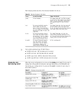
Figure 49
Network diagram for Shared VLAN configuration
Configuration Procedure
# Enable selective QinQ on Ethernet2/0/6. Refer to “Selective QinQ Configuration
Example” on page 167 for the details.
# Specify VLAN 100 as the shared VLAN on the module in slot 2.
<SW7750> system-view
[SW7750] vlan 100
[SW7750-vlan100] quit
[SW7750] shared-vlan 100 slot 2
# Add the ports of all the packets forwarded on the module in slot 2 to VLAN 100.
Refer to
“Configuring a Port-Based VLAN” on page 97
for detailed configuration.
Table 104
Display shared VLAN
Operation Command Description
Display the shared VLANs
configured for all the I/O
Modules and Fabrics in the
system
display shared-vlan
You can execute the
display
command in any
view.
Customer
Provider
Eth2/0/6 (PVID=2)
Eth2/0 /15
VLAN 3
VLAN 4
Summary of Contents for Switch 7757
Page 32: ...32 CHAPTER 1 CLI OVERVIEW...
Page 70: ...70 CHAPTER 5 LOGGING IN USING MODEM...
Page 76: ...76 CHAPTER 7 LOGGING IN THROUGH NMS...
Page 86: ...86 CHAPTER 9 CONFIGURATION FILE MANAGEMENT...
Page 120: ...120 CHAPTER 13 ISOLATE USER VLAN CONFIGURATION...
Page 126: ...126 CHAPTER 14 SUPER VLAN...
Page 136: ...136 CHAPTER 16 IP PERFORMANCE CONFIGURATION...
Page 152: ...152 CHAPTER 17 IPX CONFIGURATION...
Page 164: ...164 CHAPTER 19 QINQ CONFIGURATION...
Page 172: ...172 CHAPTER 21 SHARED VLAN CONFIGURATION...
Page 182: ...182 CHAPTER 22 PORT BASIC CONFIGURATION...
Page 198: ...198 CHAPTER 24 PORT ISOLATION CONFIGURATION...
Page 208: ...208 CHAPTER 25 PORT SECURITY CONFIGURATION...
Page 224: ...224 CHAPTER 27 DLDP CONFIGURATION...
Page 232: ...232 CHAPTER 28 MAC ADDRESS TABLE MANAGEMENT...
Page 240: ...240 CHAPTER 29 CENTRALIZED MAC ADDRESS AUTHENTICATION CONFIGURATION...
Page 280: ...280 CHAPTER 30 MSTP CONFIGURATION...
Page 348: ...348 CHAPTER 35 IS IS CONFIGURATION...
Page 408: ...408 CHAPTER 39 802 1X CONFIGURATION...
Page 412: ...412 CHAPTER 40 HABP CONFIGURATION...
Page 422: ...422 CHAPTER 41 MULTICAST OVERVIEW...
Page 426: ...426 CHAPTER 42 GMRP CONFIGURATION...
Page 480: ...480 CHAPTER 47 PIM CONFIGURATION...
Page 506: ...506 CHAPTER 48 MSDP CONFIGURATION...
Page 552: ...552 CHAPTER 51 TRAFFIC ACCOUNTING CONFIGURATION...
Page 570: ...570 CHAPTER 53 HA CONFIGURATION...
Page 582: ...582 CHAPTER 54 ARP CONFIGURATION SwitchA arp protective down recover interval 200...
Page 622: ...622 CHAPTER 58 DHCP RELAY AGENT CONFIGURATION...
Page 684: ...684 CHAPTER 61 QOS CONFIGURATION...
Page 718: ...718 CHAPTER 63 CLUSTER...
Page 738: ...738 CHAPTER 67 UDP HELPER CONFIGURATION...
Page 752: ...752 CHAPTER 69 RMON CONFIGURATION...
Page 772: ...772 CHAPTER 70 NTP CONFIGURATION...
Page 796: ...796 CHAPTER 72 FILE SYSTEM MANAGEMENT...
Page 802: ...802 CHAPTER 73 BIMS CONFIGURATION...
Page 814: ...814 CHAPTER 74 FTP AND TFTP CONFIGURATION...
Page 830: ...830 CHAPTER 75 INFORMATION CENTER...
Page 836: ...836 CHAPTER 76 DNS CONFIGURATION...
Page 852: ...852 CHAPTER 77 BOOTROM AND HOST SOFTWARE LOADING...
Page 858: ...858 CHAPTER 78 BASIC SYSTEM CONFIGURATION DEBUGGING...


