


196
C
HAPTER
24: P
ORT
I
SOLATION
C
ONFIGURATION
n
■
An Ethernet port belongs to only one port isolation group. If you add an
Ethernet port to different isolation groups, the port belongs to only the latest
isolation group to which the port is added.
■
Currently, modules of Type A (3C16860, 3C16861, LS81FS24A, 3C16858, and
3C16859) do not support the Port Isolation feature.
Displaying Port
Isolation
Configuration
After the above configuration, you can execute the
display
command in any view
to view the information about the Ethernet ports added to an isolation group.
Port Isolation
Configuration
Example
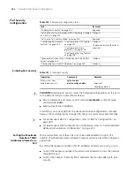
Network requirements
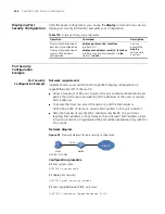
■
PC2, PC3 and PC4 connect to the switch ports Ethernet2/0/2, Ethernet2/0/3,
and Ethernet2/0/4 respectively.
■
It is desired that PC2, PC3 and PC4 are isolated from each other so that they
cannot communicate with each other.
Network diagram
Figure 52
Network diagram for port isolation configuration
Configuration procedure
# Create isolation group 1.
<SW7750> system-view
System View: return to User View with Ctrl+Z.
[SW7750] port-isolate group 1
# Add Ethernet2/0/2, Ethernet2/0/3, and Ethernet2/0/4 to the isolation group 1.
Table 128
Display port isolation configuration
Operation Command
Display the configuration of the created
isolation group
display isolate port
[
group
group-id
]
Internet
PC2
Eth2 /0/3
Eth2/0 /2
Eth2/0/4
Eth2/0/1
Switch
PC3
PC4
Summary of Contents for Switch 7757
Page 32: ...32 CHAPTER 1 CLI OVERVIEW...
Page 70: ...70 CHAPTER 5 LOGGING IN USING MODEM...
Page 76: ...76 CHAPTER 7 LOGGING IN THROUGH NMS...
Page 86: ...86 CHAPTER 9 CONFIGURATION FILE MANAGEMENT...
Page 120: ...120 CHAPTER 13 ISOLATE USER VLAN CONFIGURATION...
Page 126: ...126 CHAPTER 14 SUPER VLAN...
Page 136: ...136 CHAPTER 16 IP PERFORMANCE CONFIGURATION...
Page 152: ...152 CHAPTER 17 IPX CONFIGURATION...
Page 164: ...164 CHAPTER 19 QINQ CONFIGURATION...
Page 172: ...172 CHAPTER 21 SHARED VLAN CONFIGURATION...
Page 182: ...182 CHAPTER 22 PORT BASIC CONFIGURATION...
Page 198: ...198 CHAPTER 24 PORT ISOLATION CONFIGURATION...
Page 208: ...208 CHAPTER 25 PORT SECURITY CONFIGURATION...
Page 224: ...224 CHAPTER 27 DLDP CONFIGURATION...
Page 232: ...232 CHAPTER 28 MAC ADDRESS TABLE MANAGEMENT...
Page 240: ...240 CHAPTER 29 CENTRALIZED MAC ADDRESS AUTHENTICATION CONFIGURATION...
Page 280: ...280 CHAPTER 30 MSTP CONFIGURATION...
Page 348: ...348 CHAPTER 35 IS IS CONFIGURATION...
Page 408: ...408 CHAPTER 39 802 1X CONFIGURATION...
Page 412: ...412 CHAPTER 40 HABP CONFIGURATION...
Page 422: ...422 CHAPTER 41 MULTICAST OVERVIEW...
Page 426: ...426 CHAPTER 42 GMRP CONFIGURATION...
Page 480: ...480 CHAPTER 47 PIM CONFIGURATION...
Page 506: ...506 CHAPTER 48 MSDP CONFIGURATION...
Page 552: ...552 CHAPTER 51 TRAFFIC ACCOUNTING CONFIGURATION...
Page 570: ...570 CHAPTER 53 HA CONFIGURATION...
Page 582: ...582 CHAPTER 54 ARP CONFIGURATION SwitchA arp protective down recover interval 200...
Page 622: ...622 CHAPTER 58 DHCP RELAY AGENT CONFIGURATION...
Page 684: ...684 CHAPTER 61 QOS CONFIGURATION...
Page 718: ...718 CHAPTER 63 CLUSTER...
Page 738: ...738 CHAPTER 67 UDP HELPER CONFIGURATION...
Page 752: ...752 CHAPTER 69 RMON CONFIGURATION...
Page 772: ...772 CHAPTER 70 NTP CONFIGURATION...
Page 796: ...796 CHAPTER 72 FILE SYSTEM MANAGEMENT...
Page 802: ...802 CHAPTER 73 BIMS CONFIGURATION...
Page 814: ...814 CHAPTER 74 FTP AND TFTP CONFIGURATION...
Page 830: ...830 CHAPTER 75 INFORMATION CENTER...
Page 836: ...836 CHAPTER 76 DNS CONFIGURATION...
Page 852: ...852 CHAPTER 77 BOOTROM AND HOST SOFTWARE LOADING...
Page 858: ...858 CHAPTER 78 BASIC SYSTEM CONFIGURATION DEBUGGING...


