background image

Chapter  4.  Installing  CT28  on  the 
Horizontal Mounting Bracket

Critical information

Attention:  This wall-mount bracket is intended for installation by 
qualified professionals.

Notice:  Please read these instructions carefully and completely 
before attempting installation.

 WARNING

Improper installation or suspension of any heavy load 
can result in death or serious injury to persons, as well 
as damage to property.
It  is  the  responsibility  of  the  installation  personnel  to 
verify  and  guaranty  the  reliability  and  safety  of  the 
installation.

Notice:   This  product  must  be  installed  in  compliance  with  all 
applicable  local,  state  and  national  regulatory  provisions.  The 
responsibility rests with the installer to verify that the installation 
is carried out in accordance with any applicable legislation.

Important:   The  installer  must  assess  the  appropriate  stability 
and sturdiness of the mounting surface. In the case of wall-mount 
and  ceiling-mount  brackets,  this  includes,  but  is  not  limited  to 
verifying  the  positions  of  suitable  studs  in  the  case  of  drywall 
mounts, hollow points in concrete block or solid concrete, as well 
as the presence and vicinity of electrical wiring or plumbing.

Restriction:   Only  hardware  and  accessories  included  with 
the  product  or  specified  by  1  Sound  should  be  used  for  its 
installation.

Restriction:   Do  not  modify  or  alter  the  loudspeaker  or  any 
accessory. Any modification by the user or installer could render 
the product or the installation unsafe.

Restriction:  Do not install a loudspeaker or any accessory near 
any open flame or heat source.

Products, accessories and tools required

To install a CT28 enclosure permanently on a wall or surface using the 
Horizontal Mounting Bracket, you will need the following:

A CT28 loudspeaker enclosure

The Horizontal Mounting Bracket kit

The Angle Bar kit

An  appropriate  power  drill  and  bit  for  the  installation  surface 
material

A 4 mm hex driver and a 4 mm hex wrench (Allen)

Medium-duty  mounting  screws  or  bolts  appropriate  to  the 
mounting  surface  (coach  screws  for  drywall  studs,  concrete 
screw anchors for concrete or masonry, etc.); screws and bolts 
should have a flanged head or a coupled washer ø14-16 mm in 
order to retain the mounting plate

Appropriate  tools  for  securing  the  aforementioned  fasteners 
(power screwdriver etc.)

A torque wrench

Optional: a short two-leg steel rope bridle, 2 × M5 double-swivel 
hoist rings and appropriate tools for securing these

Recommended: pencil or marker, spirit level, stud finder

Procedures

Disassembling the Horizontal Mounting Bracket

The Horizontal Mounting Bracket ships fully assembled, but to facilitate 
installation, it should first be separated into three parts: the wall-mount 
yoke  and  the  two  end  plates  with  the  tilt-adjustment  mechanism  that 
attach to the speaker enclosure. Before disassembly, be sure to note the 
proper interlocking configuration of the tilt mechanism; this will remove 
doubts when it is time to reassemble the bracket.

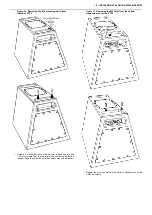
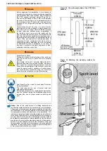
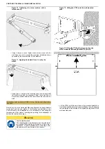
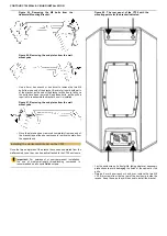
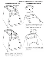
Figure   48.  Removing  the  M6  bolts  from  the 
Horizontal Mounting Bracket.

Figure  49. Removing the end plates from the wall-
mount yoke.

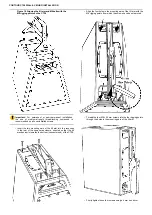
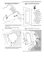
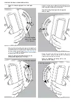
Use a 4 mm hex wrench or hex driver to remove the two M6 
bolts from one end of the bracket. Be careful to hold both parts 
of the bracket, as the end of the bracket will be free to fall once 
the bolts have been removed. Keep these bolts, as the will be 
required to reassemble the bracket once it is installed.

Summary of Contents for Contour CT28

Page 1: ...Contour CT28 Wall Ceiling Installation...

Page 2: ...tal Mounting Bracket 22 Critical information 22 Products accessories and tools required 22 Procedures 22 Disassembling the Horizontal Mounting Bracket 22 Installing the Horizontal Bracket on the CT28...

Page 3: ...ions Table 1 CT28 Specifications Description Passive compact 3 way loudspeaker lightweight horn loaded point source Bandwidth 70 Hz 18 kHz 6 dB preset dependent Max SPL 140 dB 1 m with preset Power 17...

Page 4: ...litating both vertical and horizontal positioning The bracket is made from stainless steel 316 or galvanized zinc plated steel with black or white powder coating The bracket can be used together with...

Page 5: ...Any modification by the user or installer could render the product or the installation unsafe Restriction Do not install a loudspeaker or any accessory near any open flame or heat source Products acce...

Page 6: ...hex wrench to loosen and remove the M4 16 mm pan lock bolt from the bottom of the bracket Be sure to keep this bolt as it will be necessary to fix the pan angle when the installation is completed Fig...

Page 7: ...8 25 mm pivot bolt and its washer from the top of the bracket Again be sure to keep these bolts and washers as they will be necessary to complete the installation Figure 9 Removing the top M8 pivot bo...

Page 8: ...lt assembly from the wall yoke The tilt assembly should come away from the yoke Note Before mounting the tilt assembly to the CT28 enclosure it is recommended that you unlock the tilt mechanism to ens...

Page 9: ...anism As the rotating bracket and the tilt arm move with respect to each other the moving cam should slide up and down the tilt arm and within the rotating bracket with negligible resistance IF THE ME...

Page 10: ...eep the cam in the guide without rattling but not so tight as to impede the movement of the cam in the slot If the mechanism does not move freely with negligible resistance the entire mount should be...

Page 11: ...m hex wrench or hex driver remove the two M6 25 mm screws from the top rear of the enclosure inside the recess Keep these as they will be used to mount the bracket Figure 17 Removing the M6 bolts from...

Page 12: ...rt the two mounting ears of the tilt arm into the recesses in the rear of the speaker enclosure oriented so that the tilt mechanism is towards the bottom connector end of the CT28 Align the four holes...

Page 13: ...ntal and vertical space for the speaker enclosure with the bracket attached referring to the figures below Figure 19 The necessary vertical and forward clearance for the CT28 on the Wall Bracket perpe...

Page 14: ...points on the top of the CT28 enclosure for this purpose In most cases of wall mounting a single CT28 enclosure the use of a steel wire rope safety bridle will provide sufficient redundant safety Car...

Page 15: ...e M5 eye bolts into the rigging points from which the screws were removed and tighten them with your fingers Figure 28 Tightening the eye bolts Using a slotted socket or eye bolt spanner firmly tighte...

Page 16: ...any wall or surface make sure that it does not conceal electrical wiring or conduits Consult the wiring diagram of the facility or venue and check for nearby outlets switches or junction boxes that co...

Page 17: ...r them of residue and verify the appropriate depth of each Place the mounting plate against the wall and align the four mounting holes centered on the drilled holes Insert the six screws or anchors di...

Page 18: ...nt Apply force or weight to the mounting plate to physically verify its ability to support the necessary load There must be no movement possible between the plate and the wall Installing and pointing...

Page 19: ...ttom of the rotating bracket with the holes in the top and bottom of the wall mounted yoke and insert and thread the bottom pivot bolt through its washer into the aligned holes in the yoke and bracket...

Page 20: ...olumn at maximum pan 90 Figure 41 Horizontal clearance for the CT28 on the Wall Bracket on a continuous wall at maximum pan 60 The top and bottom plates of the feature a set of holes used to set the p...

Page 21: ...the Bracket its anchor must be installed at least one speaker length away from the anchors holding the Bracket Use only steel wire ropes or steel chains that conform to applicable regulations or norms...

Page 22: ...nd tools required To install a CT28 enclosure permanently on a wall or surface using the Horizontal Mounting Bracket you will need the following A CT28 loudspeaker enclosure The Horizontal Mounting Br...

Page 23: ...be easily attached to the CT28 enclosure Important For permanent or semi permanent installation the use of medium strength thread locking compound is recommended on all user installed screws Figure 5...

Page 24: ...les in the bracket with the threaded holes in the rear of the enclosure Figure 53 Installing the Horizontal Bracket plates on the CT28 Insert the two M6 x 25 mm screws previously removed and thread th...

Page 25: ...TING BRACKET Figure 55 Removing the M6 bolts from the bottom connector end of the CT28 Figure 56 The plates of the Horizontal Bracket installed on the CT28 Repeat the previous four steps on the opposi...

Page 26: ...refully review the third party manufacturer s documentation to assure that the bridle and all its components are certified for the proper Safe Working Load with the required Factor of Safety The lengt...

Page 27: ...pendicular from the mounting surface Therefore the increased forces imposed on the fixings and wall must be taken into account Careful thought must be given to ensure that the wall structure is strong...

Page 28: ...onry concrete block or solid concrete and utilizing anchoring methods and hardware appropriate for safe installation of the equipment according to the construction material and depth of the mounting s...

Page 29: ...depth of each Place the mounting yoke against the wall in the correct orientation with the open hooks for the angle adjustment plates facing up and align the four mounting holes centered on the drill...

Page 30: ...ttached to the wall and the end plates of the bracket are installed on the CT28 enclosure the installation can be completed by re coupling the components of the bracket securing and pointing the louds...

Page 31: ...n the wall mounted yoke DO NOT release the CT28 Figure 75 Positioning the CT28 for the required coverage 30 shown As one person holds and tilts the speaker enclosure the second operator should help to...

Page 32: ...gle and thread it into the bracket Figure 79 Tightening the tilt locking bolt into the Horizontal Mounting Bracket 10 shown Using a 4 mm hex wrench tighten the first bolt firmly into the bracket so th...

Page 33: ...ket use a 4 mm hex wrench to tighten them securely These two secondary bolts serve to lock the two components of the bracket together and prevent the external plate from slipping over the head of the...

Page 34: ...t or the structure to which it is installed In most cases of wall mounting a single CT28 enclosure the use of a two leg safety bridle will provide sufficient redundant safety The legs of the bridle mu...

Page 35: ...tion by the user or installer could render the product or the installation unsafe Restriction Do not install a loudspeaker or any accessory near any open flame or heat source Products accessories and...

Page 36: ...t repeat the above process to remove the plate from the opposite end Installing the Horizontal Bracket on the CT28 Once the two end plates of the bracket have been separated from the wall mounted yoke...

Page 37: ...wo mounting holes in the bracket with the threaded holes in the rear of the enclosure Figure 90 Installing the Horizontal Bracket plates on the CT28 Insert the two M6 x 25 mm screws previously removed...

Page 38: ...ATION Figure 92 Removing the M6 bolts from the bottom connector end of the CT28 Figure 93 The plates of the Horizontal Bracket installed on the CT28 Repeat the previous four steps on the opposite bott...

Page 39: ...ndant safety Carefully review the third party manufacturer s documentation to assure that the bridle and all its components are certified for the proper Safe Working Load with the required Factor of S...

Page 40: ...nds the mass of the enclosure out to perpendicular from the mounting surface Therefore the increased forces imposed on the fixings and wall must be taken into account Careful thought must be given to...

Page 41: ...ollow points in masonry concrete block or solid concrete and utilizing anchoring methods and hardware appropriate for safe installation of the equipment according to the construction material and dept...

Page 42: ...ling for drilling When it has been verified that there is no wiring or plumbing in the wall or ceiling behind the mounting position use the Angle Bar itself as a drilling template and mark with the pe...

Page 43: ...mount shown Insert the eight screws or anchors through the mounting holes in the Angle Bar Tighten the screw anchors with your fingers only sufficiently to keep them in place Figure 108 Driving the sc...

Page 44: ...ether Important Depending on whether the installation is on a vertical wall or on a ceiling the yoke of the Horizontal Mounting Bracket must be oriented Figure 110 Aligning the Yoke with the Angle Bar...

Page 45: ...inting the loudspeaker to achieve the required coverage CAUTION Two People Required The following task simultaneously requires moderate two handed lifting and the performance of fine motor operations...

Page 46: ...their corresponding angles in the ceiling mounted configuration 0 parallel to ceiling Figure 120 The tilt locking holes and their corresponding angles in the wall mounted configuration 0 perpendicular...

Page 47: ...n page 22 through the appropriate hole for the selected angle and thread it into the bracket Figure 123 Tightening the tilt locking bolt into the Horizontal Mounting Bracket 40 shown Using a 4 mm hex...

Page 48: ...ome into contact with the external surface of the plates between the holes Figure 126 Inserting the secondary bolts 40 tilt angle shown When these two secondary bolts are threaded into the Bracket use...

Page 49: ...and Working Load Limit These must be of proper length and installed in such a position as to prevent the enclosure from falling more than 20 cm in the case of failure of the Bracket or the structure t...

Page 50: ......
Reviews: