background image

46


AMD RS880 motherboard 

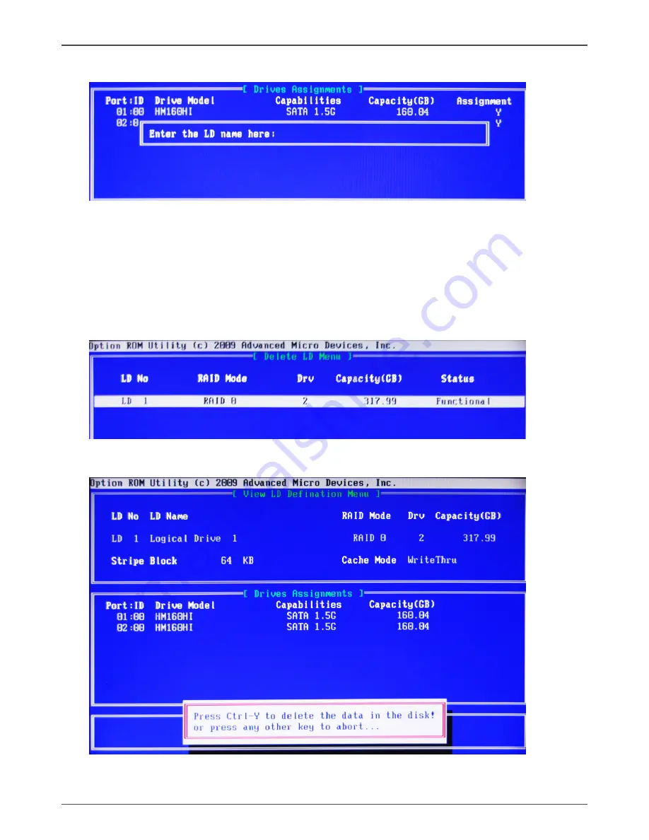
3.    Enter the LD name.

4.    Modify Array Capacity, and press <Ctrl-Y> to save the modification. When the setup 

is finished, press <Esc> to exit the RAID interface. After the PC reboots, the RAID 

controller will display the ready RAID.    

Deleting a RAID set

1.    In 

Main Menu

, select <3> to enter 

Delete LD Menu

, and select the RAID you 

       want to delete.

2.    Press <Ctrl-Y> to delete the RAID, or press any other key to abort.

Содержание M880G-ITX series

Страница 1: ......

Страница 2: ...ER OR AN EXPERIENCED AUDIO TELEVISION TECHNICIAN NOTE Connecting this device to peripheral devices that do not comply with Class B requirements or using an unshielded peripheral data cable could also result in harmful interference to radio or television reception The user is cautioned that any changes or modifications not expressly approved by the party responsible for compliance could void the us...

Страница 3: ...Header 13 USB Header 14 FP Audio Header 14 Front Panel Header 15 Speaker Header 15 Connecting Serial ATA Cables 16 Fan Connectors 16 SPDIF Out Connector 16 Expansion Slots 17 Jumper Settings 18 Configuring the BIOS 19 Enter BIOS Setup 19 Main Menu 19 X Setting Menu 20 Advanced Menu 20 CPU Configuration 20 SATA Configuration 21 USB Configuration 21 Power Configuration 21 Security 22 PCIPnP 22 Chips...

Страница 4: ...nd Software 27 Drivers Installation 27 Realtek HD Audio Driver Setup 34 Getting Started 34 Sound Effect 34 Mixer 36 Audio I O 38 Microphone 42 3D Audio Demo 43 Information 43 SATA RAID User Manual 44 Setting up the BIOS 44 Entering the RAID BIOS Setup 45 Creating a RAID set 45 Deleting a RAID set 46 Installing the RAID Drives 47 Table of Contents ...

Страница 5: ...SB 2 0 ports four on the back panel two via the USB brackets connected to the internal USB header optional v Supports wake up from S1 S3 v Supports USB 2 0 protocol up to 480 Mbps transmission rate q USB 3 0 Ports Optional v Supports hot plug and play v Two USB 3 0 ports on the back panel q Onboard Serial ATA III v Independent DMA operation on six ports optional v Data transfer rates of 600 Mb s q...

Страница 6: ...spend to DRAM supported STR v RTC timer to power on the system v AC power failure recovery q Onboard Graphics Support v Integrates HD 4200 series graphics chipset v Supports DirectX10 1 Shader Model 4 1 v HDMI and DVI I port output support q Expansion Slots v One PCI Express x1 slot v One Mini PCI Express slot Motherboard Specifications ...

Страница 7: ...ATA3 SATA2 SATA1 5 9 11 2 52 51 PCIEX1 16 Southbridge Northbridge 6 SATA5 SATA6 COM1 14 CPU 1 CPU fan connector 2 24 pinATX power connector 3 Clear CMOS jumper 4 SYS fan connector 5 Front pannel header 6 Speaker header 7 COM header 8 USB headers 9 SATA connectors 10 Southbridge 11 MINI PCI Express slot 12 PCI Express x1 slot 13 SPIDF connector 14 Front pannel audio header 15 Backpanel connectors 1...

Страница 8: ...his motherboard can support two WiFi antenna modules Refer to the following to install the WiFi antenna modules Step 1 Secure the MINI PCIe card into the MINI_PCIE1 slot with screws 120 240 121 120 240 121 1 5V 1 5V MINI_PCIE1 slot MINI PCIe card 120 240 121 120 240 121 1 5V 1 5V Screws 9 Activity LED Status Descritption Off No link Orange Linked Blinking Data activity 6 LAN port LED indicators Sp...

Страница 9: ...he same as those shown in this manual 2 Users can install one or two WiFi antennas to the motherboard 3 Users can bend or rotate the WiFi antennas to the best receiving direction according to the picture below Step 2 Secure the bracket to the motherboard with screws according to the picture below 120 240 121 120 240 121 1 5V 1 5V Step 3 Connect the WiFi wires to the MINI PCIe card as the following...

Страница 10: ...Chassis q Connecting cables and setting switches Safety Instructions To reduce the risk of fire electric shock and injury always follow basic safety precations Remember to remove power from your computer by disconnecting the AC main source before removing or installing any equipment from to the computer chassis Preparing the Motherboard The motherboard shipped in the box does not contain a CPU and...

Страница 11: ...efer to the following recommendations to install the memory modules Note that a memory module has a notch so it can only fit in one direction Refer to the following procedure to install memory modules into the slots on the motherboard 1 Unlock a DIMM slot by pressing the module clips outward 2 Align the memory module to the DIMM slot and insert the module vertically into the DIMM slot The plastic ...

Страница 12: ...ust and foreign objects and promotes correct airflow within the chassis Before installing the motherboard install the I O shield from the inside of the chassis Press the I O shield into place and make sure it fits securely If the I O shield does not fit into the chassis you would need to obtain the proper size from the chassis supplier Securing the Motherboard into the Chassis Most computer chassi...

Страница 13: ...wer Connectors v 24 pin ATX Power Connector v 4 pin ATX_12V Power Connector q Internal Headers Connectors v COM Header v USB Header v Front Pannel Audio Header v Front Panel Header v Speaker Header v SPDIF Out Header q Serial ATA SATA Connectors q Fan Connectors q Expansion Slots q Jumper Settings See Figure 1 to locate the connectors and jumpers referenced in the following procedure ...

Страница 14: ...pins are properly aligned with the connector on the motherboard Firmly plug the power supply cable into the connector and make sure it is secure 120 240 121 120 240 121 1 5V 1 5V PWR1 1 12 13 24 1 PWR2 4 pin ATX_12V Power Connector PW2 the 4 pin ATX 12V power connector is used to provide power to the CPU Align the pins to the connector and press firmly until seated PWR2 Pin Definition Pin Signal 1...

Страница 15: ...0 121 1 5V 1 5V FP_USB1 1 FP Audio Header The audio connector supports HD audio standard and provides two kinds of audio output choices the Front Audio the Rear Audio The front Audio supports re tasking function Note In order to utilize the front audio header your chassis must have front audio connector Also please make sure the pin assignment on the cable is the same as the pin assignment on the ...

Страница 16: ...y button q HDD LED Attach the hard disk drive indicator LED cable to these two pins The HDD indicator LED indicates the activity status of the hard disks q RST SW Attach the Reset switch cable from the front panel of the case to these two pins The system restarts when the RESET switch is pressed Note Some chassis do not have all four cables Be sure to match the name on the connectors to the corres...

Страница 17: ... Pin Definition Pin Signal 1 GND 2 TXP 3 TXN 4 GND 5 RXN 6 RXP 7 GND Fan Connectors There are two fan connectors on the motherboard The fan speed can be detected and viewed in the PC Health section of the CMOS Setup SPDIF Out Connector This connector provides a SPDIF Sony Philips Digital Interface output to digital multimedia device through coaxial connector CN5 Pin Definition Pin Signal 1 GND 2 S...

Страница 18: ...CI Express slot Mini PCI Express Slot MINI_PCIE1 There is one Mini PCI Express slot reserved for the WiFi Module PCI Express x1 Slot PCIEX1 There is one PCI Express x1 slot that is designed to accommodate less bandwidth intensive cards such as a modem or LAN card 120 240 121 120 240 121 1 5V 1 5V MINI_PCIE1 PCIEX1 1 51 2 52 ...

Страница 19: ... chapter whenever in doubt Notice 1 Be sure to save the CMOS setting when exit the CMOS 2 If the CPU is frequency multiplier locked no CPU speed change will be seen even if the frequency multiplier setting in CMOS setup is changed JP1 Clear CMOS JP1 Selection 1 2 Normal 2 3 Clear CMOS 1 1 If you want to clear the system configuration use the JP1 Clear CMOS Jumper to clear data Close Open Default s...

Страница 20: ... the BIOS Setup Utility Note 1 We reserve the right to update the BIOS version presented in the manual The BIOS pictures shown in this section are for reference only 2 It is strongly recommended that you do not change the default BIOS settings Changing some settings could damage your system Main Menu This menu gives you an overview of the general system specifications The BIOS automatically detect...

Страница 21: ... menu show the CPU related information that the BIOS automatically detects Press enter to display the configuration options q GART Error Reporting Allows you to enable or disable GART Graphics Address Remapping Table Error Reporting function q Microcode Update Allows you to enable or disable Microcode Update q Secure Virtual Machine Mode This item allows you to enable or disable AMD s SVM Secure V...

Страница 22: ...ntroller Mode Allows you to configure the USB 2 0 controller in HiSpeed or Full Speed q BIOS EHCI Hand Off Allows you to enable support for operating systems without an EHCI hand off feature q Legacy USB1 1 HC Support Allows you to enable or disable Legacy USB1 1 HC support q USB Mass Storage Device Configuration Allows you to configure USB Mass Storage Device Power Management The items in this me...

Страница 23: ...sword PCIPnP The items in this menu show the function of PCI bus system and PnP Press enter to display the configuration options q Clear NVRAM The items allow you to select whether clear NVRAM during system boot q Plug and Play O S When set to No BIOS configure all the devices in the system When set to YES and if you install a Plug and Play operating system the operating system configures the Plug...

Страница 24: ...on OnBoard Device Configuration The items allow you to configure onboard device including HD Audio LAN and so on PC Health Menu Select PC Health from the BIOS Setup Utility menu to display the System menu q IRQ3 4 5 7 9 10 11 14 15 These items allow you to set the Interrupt Request q DMA Channel 0 1 3 5 6 7 Use these items to set the Direct Memory Access Channel q Reserved Memory Size This item al...

Страница 25: ...crease the time needed to boot the system When set to Disabled BIOS performs all the POST items q Fullscreen LOGO Show Enable or disable fullscreen LOGO show q AddOn ROM Display Mode Sets the display mode for option ROM q Bootup Num Lock Allows you to select the power on state for the NumLock q Wait for F1 If Error When set to Enabled the system waits for the F1 key to be pressed when error occurs...

Страница 26: ...s to fields other than system date system time and password the BIOS asks for a confirmation before exiting Discard Changes This option allows you to discard the selections you made and restore the previously saved values After selecting this option a confirmation appears Select Ok to dis card any change and load the previously saved values Load Optimal Defaults This option allows you to load the ...

Страница 27: ...d or downloaded and the utility program AFUDOS XX exe to the diskette 2 Allow the PC system to boot from the DOS diskette 3 At the DOS prompt type AFUDOS XX ROM P C B N X ENTER Note XX the BIOS file name can be defined by users 4 Wait until the flash update is complete 5 Restart the PC Warning Do not turn off or RESET the computer during the flash process If you are not sure how to upgrade the BIO...

Страница 28: ... installation pictures shown in this section are for reference only 3 To ensure a successful installation please install Microsoft net framework 2 0 or Windows XP SP3 or later version before installing the driver CD The kit comes with a CD that contains utility drivers and additional software Drivers Installation 1 Insert the driver CD into the drive after loading your operating system and then yo...

Страница 29: ...28 AMD RS880 motherboard ...

Страница 30: ...29 Installing Drivers and Software Note If the software Microsoft net Framework 2 0 has not been installed the failure report will display Failures occurred during installation ...

Страница 31: ...motherboard 3 Left click Realtek HD Audio driver and follow the instructions below to install the sound driver 4 Left click Realtek PCIE network Driver and follow the instructions below to install the network driver ...

Страница 32: ...31 Installing Drivers and Software 5 Left click Renesas USB3 0 Driver and follow the instructions below to install the USB3 0 host driver Note USB 3 0 port would not work in POST CMOS setup and DOS mode ...

Страница 33: ...32 AMD RS880 motherboard 6 Left click Atheros Wireless driver and follow the instructions below to install the wireless driver ...

Страница 34: ...33 Installing Drivers and Software 7 At last you can enter Device Manager interface that provides information about the hardware devices on this motherboard and check if the installation is finished ...

Страница 35: ... the control panel will appear Sound Effect After clicking on the Sound Effect tab 3 sections Environment Equalizer and Karaoke are available for selection Environment Simulation You will be able to enjoy different sound experience by pulling down the arrow totally 23 kinds of sound effect will be shown for selection Realtek HD Audio Sound Manager also provides five popular settings Stone Corridor...

Страница 36: ...ently used for your quick enjoyment How to Use Other than the buttons Pop Live Club Rock shown on the page to pull down the arrow in Others you will find more optimized settings available to you Karaoke Mode Karaoke mode brings Karaoke fun back home by simply using the music you usually play Karaoke mode can help you eliminate the vocal of the song or adjust the key to accommodate your range Vocal...

Страница 37: ...u to create your favorite sound effect in one single tool Playback control Mute You may choose to mute single or multiple volume controls or to completely mute sound output Tool Show the following volume control This is to let you freely decide which volume control items to be displayed total 13 items to be chosen Advanced controls Enable playback multi streaming ...

Страница 38: ...o mute single or multiple volume controls or to completely mute sound input Tool Show the following volume controls This is to let you freely decide which volume control items to be displayed Advanced controls Advanced control is a Microphone Boost icon Once this item is checked you will find advanced icon beside Front Pink In Mic Volume With this the input signal into Front Pink In Mic Volume wil...

Страница 39: ...unctions Instead now each jack is able to be chosen to perform either output i e playback function or input i e Recording function we call this Retasking Audio I O aims to help you setting jacks as you wish Moreover other than blue to blue pink to pink the way that you used to do Audio I O would guide you to other right jacks that can also serve as microphone speaker headphone ...

Страница 40: ...evice will pop up for your selection Please select the device you are trying to plug in If the device is being plugged into the correct jack you will be able to find the icon beside the jack changed to the one that is same as your device If not correct Realtek HD Audio Manager will guide you to plug the device into the correct jack ...

Страница 41: ... so called AC 97 jacks If so please check this item to disable front panel jack detection Enable auto popup dialogue when device has been plugged in Once this item checked the dialog Connected device would not automatically pop up when device plugged in S PDIF Short for Sony Philips Digital Interface a standard audio file transfer format S PDIF allows the transfer of digital audio signals from one...

Страница 42: ...Audio Output Source Output digital audio source The digital audio format such as wav mp3 midi etc will come out through S PDIF Out Speaker Calibration After you have successfully plugged in speakers and assigned to the right jacks you are only one more step to go to enjoy the intended sound We provide Speaker Calibration to help you check if the speakers are located in the correct position channel...

Страница 43: ...will get the best quality if you chose 90 position which we recommend you to use this ef fectively means that you speak right into the microphone Note A Stereo Microphone is required when using Beam Forming function Acoustic Echo Cancellation This function prevents playback sound from being recorded by microphone together with your sound For example you might have chance to use VOIP function throu...

Страница 44: ...udio Demo The section 3D Audio Demo grants you another possibility to enjoy your sound The Audio Demo allows you to listen to sound in an extraordinary way This section provides information about your current system audio device Information ...

Страница 45: ... select the Item SATA Configuration 3 Press Enter to display SATA and AHCI Configuration then select the item OnChip SATA Type 4 Press Enter and enable the option RAID 5 Enable the disks that you want to use as RAID disks 6 Press F10 to save the configuration and exit The PC reboots 7 Enter the RAID BIOS Setup by pressing F10 when prompted and proceed to set up the RAID BIOS as described in the ne...

Страница 46: ... the space bar to select a RAID Mode The supported RAID modes include Mirroring RAID 1 Striping RAID 0 and Stripe Mirroring RAID 10 The following is an example of RAID 0 array creation b If RAID 0 Striping is selected you can manually set the striping block size In the Striping Block field use the UP or DOWN ARROW key to set the Striping Block size The KB is standard unit of Striping Block size We...

Страница 47: ...on When the setup is finished press Esc to exit the RAID interface After the PC reboots the RAID controller will display the ready RAID Deleting a RAID set 1 In Main Menu select 3 to enter Delete LD Menu and select the RAID you want to delete 2 Press Ctrl Y to delete the RAID or press any other key to abort ...

Страница 48: ...ete the RAID BIOS setup boot from the windowsXP CD The Windows Setup program starts 2 Press F6 and wait a few moments for the Windows Setup screen to appear 3 Specify the AMD drivers a Insert the floppy that has the RAID driver and select the SCSIAdapter then press Enter ...

Страница 49: ...48 AMD RS880 motherboard b When the window below display press S to use the driver on floppy c Press Enter to continue the windows setup 291 MA159 01 ...

Страница 50: ...2 9 1 MA 1 5 9 0 1 8 3 F ...

Отзывы: