background image

© Copyright 2014 Zoeller

®

 Co. All rights reserved.

SERVICE CHECKLIST


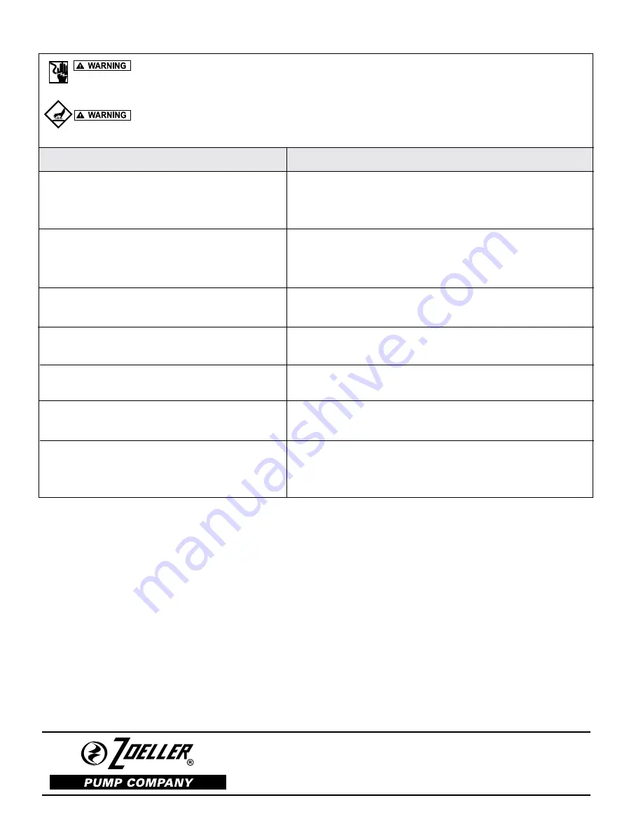
Electrical precautions. Before servicing the pump, always shut off the main power circuit. Make sure you are wearing 

insulated protective sole shoes and not standing in water. Under flooded conditions, contact your local electric company or a qualified 

licensed electrician for disconnecting electrical service to the pump prior to removal.


Pumps contain oil which becomes pressurized and hot under operating conditions. Allow 2-1/2 hours after shut down 

before servicing pump.

 Condition

  A.  Pump will not start or run.

  B.  Motor overheats and trips on overload.

  C.  Pump will not shut off.


D.  Pump operates but delivers little or no water.


  E.  Pump starts and stops too often.

  F.  Large red flashing light comes on at control  box.

  G.  Grease and solids accumulate in pit around pump.

Common Causes

Blown panel or circuit breaker fuse, low voltage, thermal overload open,  impeller 

clogged, float switch held down or defective, incorrect wiring in control panel, water 

in cap assembly.

Incorrect voltage, impeller  blocked, negative head (discharge lower than intake of pump).   

Pump runs continuously at low water level. Low oil level in motor shell.

Air lock, debris under float assembly, incoming sewage exceeds capacity of pump.

Intake clogged with grease or sludge, pump air locked (clear vent hole), low or 

incorrect voltage, clogged discharge line, operating near shut-off head.

Check valve stuck open. Sump pit too small to handle incoming sewage. Level control 

out of adjustment. Thermal overload tripping.

High water in pit. Check pump for clogging, or overload trip. See “A” and 

“D” above.

Break up solids and run pump with water running into the pit. Allow level to lower 

to the pump intake.  Continue until solids are cleared from the pit. Do not drain 

kitchen grease down the sink.

MAIL TO:  P.O. BOX 16347 • Louisville, KY  40256-0347

SHIP TO:  3649 Cane Run Road • Louisville, KY  40211-1961

(502) 778-2731 • 1 (800) 928-PUMP • FAX (502) 774-3624

Your Peace of Mind is Our Top Priority


®

®

visit our web site:

www.zoeller.com

Содержание 161-0059

Страница 1: ...X161 X163 X165 X185 X186 X188 X189 X191 ZOELLER HAZARDOUS ENVIRONMENT PUMPS For Class I Division 1 Groups C D Applications Explosion Proof Motors Model Number ______________ Date Code _______________ Simplex Duplex Job Name ____________________________________________ Distributor ____________________________________________ Date of Purchase _________ Zoeller S O No ______________ Contractor ______...

Страница 2: ... fittings be used and the pit be 36 or larger in diameter 3 INFORMATION VENTHOLEPURPOSE Itisnecessarythatallsubmersible pumps capable of handling various sizes of solid waste be of the bottom intake design to reduce clogging and seal failures If a check valve is incorporated in the installation a vent hole approx 3 16 must be drilled in the discharge pipe below the check valve and pit cover to pur...

Страница 3: ...6 10 0 L 38 8 34 5 DX186 1 1 2 3450 230 1 60 13 7 9 3 45 7 H EX186 1 1 2 3450 230 1 60 13 7 9 3 45 7 H 1 29 1 05 HX186 1 1 2 3450 200 1 60 17 2 11 8 54 5 J IX186 1 1 2 3450 200 1 60 17 2 11 8 54 5 J 86 71 JX186 1 1 2 3450 200 3 60 10 3 6 0 45 2 M 2 62 2 14 FX186 1 1 2 3450 230 3 60 9 2 5 5 39 4 M 3 52 2 8 GX186 1 1 2 3450 460 3 60 4 6 2 8 19 7 M 13 9 11 3 DX188 1 1 2 3450 230 1 60 14 0 7 4 45 7 H ...

Страница 4: ... L 38 8 34 5 DX294 1 1 2 3450 230 1 60 13 7 9 7 45 7 H EX294 1 1 2 3450 230 1 60 13 7 8 1 45 7 H 1 29 1 05 HX294 1 1 2 3450 200 1 60 17 8 10 1 54 5 J IX294 1 1 2 3450 200 1 60 17 8 10 1 54 5 J 86 71 JX294 1 1 2 3450 200 3 60 10 8 5 3 45 2 M 2 62 2 14 FX294 1 1 2 3450 230 3 60 9 5 5 6 39 4 M 3 5 2 8 GX294 1 1 2 3450 460 3 60 4 8 2 3 19 7 M 13 9 11 3 BAX294 1 1 2 3450 575 3 60 3 8 2 2 15 9 M 20 6 18...

Страница 5: ... required for installation of hazardous environmental pump 2 Installationandpipinginstructionsareincludedwiththerailsystem and basin instructions If pump is being retrofitted to an existing rail system accessory parts may be required Consult the factory and advise make and model of rail system being used 3 Allelectricalconnectionsincludingpumptocontrolboxandpower supply to control panels must comp...

Страница 6: ...40 320 400 30 40 50 60 70 80 100 90 X282 560 480 640 150 130 120 140 X292 170 160 180 X284 80 14 12 10 8 TOTAL DYNAMIC HEAD 25 30 35 40 45 22 20 18 16 50 55 60 65 70 METERS FEET X293 800 X295 210 200 X294 220 MODEL Shut off Head 70 60 50 40 30 21 3 18 3 15 2 12 2 9 1 25 20 15 10 5 Feet 3 0 7 6 6 1 4 6 Meters 1 5 X282 26 ft 7 9m 363 96 34 64 129 242 127 Gal 481 Liters 75 24 PUMP PERFORMANCE CURVE M...

Страница 7: ...ONDUIT CONNECTION 24 15 16 21 1 2 4 29 32 125 mm 6 1 16 154 mm 116 mm 222 mm 165 mm 116 mm 217 mm 633 mm 546 mm SK2506 5 127 mm 8 9 16 217 mm 6 5 16 160 mm 2 NPT OR 3 NPT FLANGE AVAILABLE 5 127mm 8 9 16 217 mm 1 1 2 NPT CONDUIT CONNECTION 25 3 16 640 mm 21 3 4 552 mm 6 5 16 160 mm SK2507 X280 Series SK1914 6 1 2 165 mm 8 3 4 222 mm 22 31 32 566 mm 4 9 16 116 mm 4 9 16 116 mm 23 9 32 591 mm CHECK V...

Страница 8: ...rain relief Installation and checking of electrical circuits and hardware should be performed by a qualified licensed electrician EXPLOSION PROOF WIRING DIAGRAMS X160 X180 X190 X280 X290 X400 SERIES All installation of controls protection devices and wiring should be done by a qualified licensed electrician All electrical and safety codes should be followed including the most recent National Elect...

Страница 9: ...9 Copyright 2014 Zoeller Co All rights reserved PUMP WIRING INSTRUCTIONS continued 016889 016890 SINGLE PHASE AUTOMATIC MODEL X282 SINGLE PHASE AUTOMATIC MODELS X160 X290 ...

Страница 10: ...onnect power and switch any two power leads Turn power back on and retest for proper rotation SENSOR WIRES See pages 8 and 9 The power and sensor wires are contained in the same cord The green wire is a ground connection All wires must terminate in the control panel The following should be noted 1 The thermal sensors are normally closed and mounted adjacent to the motor windings If internal temper...

Страница 11: ...ecks Pump power cables and control floats properly installed and voltage verified Conduit connections to panel are properly sealed After installing the pump into the containment area with adequate submer gence open the discharge valve fully Start the unit using manual controls If flow is appreciably less than rated performance pump may be air locked To expel trapped air jog the unit several times ...

Страница 12: ...ad open impeller clogged float switch held down or defective incorrect wiring in control panel water in cap assembly Incorrectvoltage impeller blocked negativehead dischargelowerthanintakeofpump Pump runs continuously at low water level Low oil level in motor shell Air lock debris under float assembly incoming sewage exceeds capacity of pump Intake clogged with grease or sludge pump air locked cle...

Отзывы: