background image

Pelletherm V.4 LT 


43 


8.  WIRING  DIAGRAM  OF  A  BOILER  FROM  SERIES  “PELLETHERM  V.4  LT”  IN 

COMBINATION WITH A PELLET BURNER FROM SERIES “GP XX SC”. 


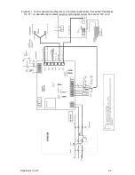
The  control  panel  wiring  diagram  of  a  hot  water  boiler  from  series  “Pelletherm  V.4  LT”, 
operating in combination with pellet burner from series “GP x sc”, is presented on Figure 8.1.  


The connectors CONN1 – CONN3 and the NTC sensor are installed in  
the boiler.  
TD – Thermo-disc (installed on the pellet burner inlet feeding pipe) -95

0

 C. 

Remove the bridge connection in CONN2, if using a room thermostat!  
Use the room thermostat socket only. Do not supply external voltage!


Remove the bridge connection when using a room thermostat!  
Use the room thermostat socket only. Do not supply external voltage!  
See the wiring diagram!  

 
Figure 8.2 presents the wiring diagram to connect a pellet burner from series “GP xx sc” to 
the connector panel of the boiler from series “Pelletherm V.4 LT”, positioned on its rear side.  
 

The wiring diagram of an automated pellet burner from series “GP xx sc” is  
presented in its manual book.  


Putting NTC sensor is required in the cartridge located in pipe hot water outlet 
with a clamp. 
This is an operation related to safety and should be performed by a trained 
person!!  

Содержание GP ** sc

Страница 1: ...1 MANUAL FOR INSTALLATION OPERATION AND MAINTENANCE OF A SYSTEM CONSISTING OF A HOT WATER PELLET BOILER FROM SERIES PELLETHERM V 4 LT AND AN AUTOMATED PELLET BURNER FROM SERIES GP xx sc http www green...

Страница 2: ...ture company thanks you for your choice The manufacture company submits this manual to help the team that will install adjust and service the system hot water pellet boiler and pellet burner as well a...

Страница 3: ...G SECTION COVER CAP 25 5 4 6 INSTALLATION OF THE COVER FLAP IN FRONT OF THE FLUE GAS OUTLET 25 5 4 7 INSTALLATION OF THE BOILER S HORIZONTAL COVER PANELS 27 5 4 8 INSTALLATION OF THE COVER OVER THE BO...

Страница 4: ...from series GP xx sc All legal provisions regarding safety All legal provisions regarding environment protection Provisions regarding installation start and adjustment All harmonized provisions of th...

Страница 5: ...y the boiler s body heat exchanging surfaces and is then transferred to the heat carrier filled in the system The hot water boiler s delivery kit from series Pelletherm V 4 LT includes Heat exchanger...

Страница 6: ...trical which ensures its usage in systems with programmable room thermostat Automatic system operation availability to regulate it through room thermostat weekly programmer guaranteeing maximum heat c...

Страница 7: ...hot water boiler s part is the boiler body heat exchanger unit as the automated pellet burner from series GP xx sc is mounted on its side The heat exchanger is offered in 2 variants the so called lef...

Страница 8: ...e has been overheated resulting from emergency situations Photo sensor for dynamic control of the burning process System for modulation of the firing air flow rate during the process of initial fuel i...

Страница 9: ...Energy efficiency class according to regulation U 2015 1187 Efficiency at nominal heating output mode 92 92 92 CO emissions in the flue gases 0 C 1013 mbar at 10 2 mg m3 163 0 Dust emissions in the fl...

Страница 10: ...let burner model GP 20_18 sc GP 25 sc GP 32 sc Boiler weight kg 342 342 362 Boiler water volume l 50 50 60 System overall dimensions B 546 1080 780 1250 546 546 546 W 1080 1080 1080 D 780 780 780 H 12...

Страница 11: ...d fuel cogeneration boiler no Combination boiler no Fuel Preferred fuel only one Other suitable fuel s Log wood moisture content 25 no no Chipped wood moisture content 15 35 no no Chipped wood moistur...

Страница 12: ...fficiency Auxiliary electricity consumption At rated heat output el n At rated heat output elmax 0 156 kW At 30 50 of rated heat output if applicable elmin 0 134 kW Of incorporated secondary emission...

Страница 13: ...moisture content 15 35 no no Chipped wood moisture content 35 no no Compressed wood in the form of pellets or briquettes yes no Sawdust moisture content 50 no no Other woody biomass no no Non woody b...

Страница 14: ...fficiency Auxiliary electricity consumption At rated heat output el n At rated heat output elmax 0 156 kW At 30 50 of rated heat output if applicable elmin 0 134 kW Of incorporated secondary emission...

Страница 15: ...moisture content 15 35 no no Chipped wood moisture content 35 no no Compressed wood in the form of pellets or briquettes yes no Sawdust moisture content 50 no no Other woody biomass no no Non woody b...

Страница 16: ...output if applicable elmin 0 134 kW Of incorporated secondary emission abatement equipment if applicable In standby mode PSB 0 013 kW Contact details Ekoterm Proekt EAD ZMM Haskovo AD 6300 Haskovo 67...

Страница 17: ...erm V 4 LT 17 Figure 4 2 System overall sizes front view Figure 4 3 Overall and connection sizes dimensions of a hot water pellet boiler from series Pelletherm V 4 LT pellet burner mounting flange sid...

Страница 18: ...Pelletherm V 4 LT 18 Figure 4 4 Overall and connection sizes dimensions of the system rear view Figure 4 5 Overall and connection sizes dimensions of the system top view...

Страница 19: ...oiler from series Pelletherm V 4 LT and a pellet burner from series GP xx sc Boiler s convections tract cover Boiler s combustion chamber cover Boiler s combustion chamber cover panel Pellet burner mo...

Страница 20: ...cording to standard EN ISO 17225 2 2014 is presented in the automated pellet burner from series GP xx sc manual book Ash container Boiler s combustion chamber door Boiler s combustion chamber First pa...

Страница 21: ...et burner from series GP xx sc depends on The adjusted operational heating output of the burner The contamination level on the boiler s heat exchanging surfaces The sealing level of the boiler combust...

Страница 22: ...nt of the boiler must be at least 1000 mm The minimum allowed distance between the boiler s rear side and a wall must be at least 400 mm The minimum distance between the boiler side where the pellet b...

Страница 23: ...nnect the hot water pellet boiler from series Pelletherm V 4 LT to the heating installation by using proper fittings and accessories to be performed in accordance to the preliminary prepared technical...

Страница 24: ...ing of the pellet burner After the burner has been mounted the connection screws must be tightened equally in order to ensure proper sealing between the flange and the boiler body Figure 5 3 View of m...

Страница 25: ...F THE ASH CLEANING SECTION COVER CAP Figure 5 5 The cover cap for cleaning of the ash residues positioned after the second flue pass of a hot water boiler from series Pelletherm V 4 LT is properly pos...

Страница 26: ...rmal loads therefore it symmetrically manufactured It is recommended to turn the cover flap on every two to three weeks of operation Figure 5 6 The directing cover flap is dismounted and the boiler s...

Страница 27: ...letherm V 4 LT 5 4 8 INSTALLATION OF THE COVER OVER THE BOILER S CONVECTION TRACT This cover is equipped with protection element made of stainless steel Figure 5 9 Directing cover over the boiler s co...

Страница 28: ...l There are connectors to power supply to burner and to room thermostat Depending on whether it is with left or right burner mounting the connectors are positioned on the same boiler cover side as the...

Страница 29: ...to change the system construction without engagement to inform the end users 5 4 13 CONNECTING THE SYSTEM TO THE POWER SUPPLY Connecting the system consisting of a hot water pellet boiler from series...

Страница 30: ...ay mixing valve 10 Circulations pump 2 The exemplar hydraulic scheme is only informative and can not be practically used as implemented hydraulic scheme The installation and warm tests completion of t...

Страница 31: ...When initiating the system to operation consisting of a hot water pellet boiler from series Pelletherm V 4 LT and a pellet burner from series GP xx sc the following main requirements must be observed...

Страница 32: ...rheating It is factory adjusted to stop the automated pellet burner from series GP xx sc power supply in case the circulation water temperature exceeds the limit adjusted in the factory to 95 o C Swit...

Страница 33: ...Description of the electrical connectors installed on the boiler s interface panel Room thermostat connector Switch START Communication connector Pellet burner connector Emergency thermostat Switch PO...

Страница 34: ...and also to check the chimney condition The same effect might occur during the transition seasons autumn and spring when the natural chimney draught is decreased due to high ambient temperatures If th...

Страница 35: ...ON the button POWER but only after the failure reason has been eliminated The ash content does not change significantly the fuel s calorific value but requires special construction of the burner in or...

Страница 36: ...n be performed by decreasing the burner s heating output level For detailed information see the burner s manual book Do not decrease the burner s heating output below the system s minimum output becau...

Страница 37: ...ted in its manual book In case the system operation is stopped a complete cleaning from the ash residues over the boiler s heat exchanging surfaces must be performed because the ash has corrosive infl...

Страница 38: ...ompany that services and maintains the system 6 8 USER INTRODUCTION TO THE PROCEDURES FOR MAINTENANCE AND ADJUSTMENTS OF THE SYSTEM It is necessary that the user is completely introduced with the pres...

Страница 39: ...e boiler s bottom gather the ash residues in fire proof or another proper container after that in reverse order mount the ash container back and close the door mount the other cover panels of the boil...

Страница 40: ...the hot water pellet boiler Risks from electrical shock by indirect contact The boiler and the burner are connected to the power supply network and the control modules are positioned in the interface...

Страница 41: ...ut It is necessary to adjust the burner s heating output level High temperature assignment by the room thermostat if connected It is necessary to decrease the room thermostat temperature assignment 3...

Страница 42: ...er the combustion chamber surfaces inside the boiler Low temperature of the inlet water Adjust the circulations pump thermostat The recommended circulations water operational temperature is at least 6...

Страница 43: ...using a room thermostat Use the room thermostat socket only Do not supply external voltage Remove the bridge connection when using a room thermostat Use the room thermostat socket only Do not supply e...

Страница 44: ...Pelletherm V 4 LT 44 Figure 8 1 Control panel wiring diagram of a hot water pellet boiler from series Pelletherm V 4 LT co operating as a system together with a pellet burner from series GP xx sc...

Страница 45: ...Pelletherm V 4 LT 45 Figure 8 2 Wiring diagram of the boiler s connector panel used to connect the pellet burner...

Страница 46: ...Pelletherm V 4 LT 46...

Страница 47: ...dical maintenance presented in the present manual book are not observed Attempts to recover any defects performed by the buyer or by other unauthorized persons Changes in the system s appliances const...

Страница 48: ...Pelletherm V 4 LT 48...

Отзывы: