Pull out
Doorframe
Magnetic Lock
Door frame
Door frame
double-door pull out type
D-sucking disk
Ar
ma
tur
e P
lat
e
Diagram 2
Screw
Door frame
Magnet body
Armature Plate
Rubber ring
H/L-Sucking disk
T-Sucking disk
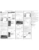
N O N C C O M
COM
NC
NO
Di ag ram 1( 12 VDC )
Ci rcuit diagram for L-type
cable only
1 2 3 4
JP
1 2 3 4
JP
Di ag ram 3( 24 VDC )
The prod ucts normally use
12VDC. (See Diagram2)
If use 24VDC, please take
the JP 2 and 3 connected.
(See Diagram1)
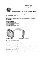
Magnetic Lock Installation Drawing
AP-180D
AP-280D(LED)
AP-350D(LED)
AP-500D(LED)
AP-180
AL-280(LED)
AP-350(LED)
AP-500(LED)
AL180M
H
11
12
12
14 .5
11
12
12
14 .5
11
G
32
38
48
58
32
38
48
58
33
F
13 0
18 5
18 5
18 4. 5
13 0
18 5
18 5
18 4. 5
13 0
F
21
24 .8
27 .3
37 .5
E1
21
24 .8
27 .3
37 .5
F2
18 2
D
6
6
6
7
D1
6
6
6
7
C
21
24 .5
27 .5
38 .5
C1
21
25
27 .5
37 .5
B
35
42
48
70
B1
35
42
48
63
A
33 2
50 6
50 6
56 0
A1
16 6
25 3
25 3
28 0
D-Sucking Disk
H/L Sucking Disk
T-sucking Disk
Series /Model
Dimension Identification
Electric Strike Series
Magnetic Lock Series
El ect ric Bolt Lock ser ies
Brackets and Accessories
Me cha ni cal Lo ck Se riess
El ec tron ic Lo ck Se ries
Electric Strike Series
Magnetic Lock Series
El ect ric Bolt Lock ser ies
Brackets and Accessories
Me cha ni cal Lo ck Se riess
El ec tron ic Lo ck Se ries
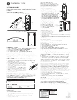
Push in
Armature
plate
Wiring Description (see Fig.1)
Precautions for installation of adsorption plate:
1.The rubber ring in the accessory bag must be installed between the adsorption plate and the door to ensure impulse force and balance the
contact between each other.
2.The screw fixing the adsorption plate shall not be tightened excessively. Allow proper resilience for the rubber ring to make it available for
adjusting the adsorption plate to the correct position so as to produce maximal adsorption force. (See Fig.2)
Armature
plate
Armature
plate
Magnetic Lock
Magnetic Lock
Armature
plate
A2
B2
C2
D2
E2
166
35
21
198
20