
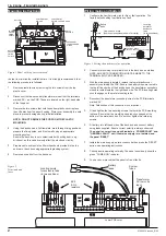

External wiring
The external wiring should now be connected to the fire panel.
The fire panel is supplied with End Of Line Resistors for the zone and
sounder circuits, these must be transferred to the last device in the circuit.
The End Of Line Resistor must be replaced with Active End Of Line
device if removable smoke/heat detectors are used on the zone cirucit..
Please note these units are polarised.
1
DISCONNECT MAINS SUPPLY & BATTERY.
2
Connect the zone wiring, one zone at a time, transferring either the
End Of Line Resistor or Active End Of Line Device, if removable
smoke/heat detectors are being employed. The active end-of-line
devices are polarised and should be connected with Red/Orange
wire to the +ve and Black to the –ve.
3
Repeat the above procedure until all the required circuits are
connected.
4
Connect the sounder wiring one circuit at a time, transferring the end
of line resistor to the last sounder on that circuit.
5
Repeat the above procedure until all the required sounder circuits are
connected.
6
Connect other external circuits as required
7
Reinstate the mains supply, enter access code then press the
‘RESET’ button.
8
Refit plastic fascia. Do not over tighten two retaining screws.
61640610 issue 6_8/02
3
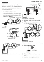
1 & 2 zone - Fire alarm panels
-
+
END-OF-LINE
RESISTOR 8K2 Ohms
fitted to last sounder
- +
2
FIRE PANEL
SOUNDERS
- +
1
+
-
-
+ +
-
-
+ +
-
Polarised and suppressed
sounders only
2nd
SOUNDER
COMMON
1st
SOUNDER
-
-
-
-
+
+
END-OF-LINE RESISTOR
8K2 Ohms fitted to last sounder
Volume
Figure 6 Connecting the Sounder circuit
COMMON
470 Ohms
680 Ohms
CALL POINT
- +
1
DETECTOR
ZONE
FIRE PANEL
COMMON
470 Ohms
680 Ohms
CALL POINT
black
red or
orange
Active
end of line
Fit an active end of line if
detectors are also connected
to the zone circuit.
8K2
Ohms
Figure 5 Connecting the manual call points
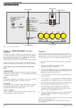
Base of existing range of detectors
- +
1
DETECTOR
ZONE
FIRE PANEL
L2
L1
OUT
IN L1
DIODE
(SCHOTTKY)
L2
L1
OUT
IN L1
DIODE
(SCHOTTKY)
Black
Red or
Orange
Active
End of Line
-
+
Remote
LED
LED
module
Connecting LED to base
with LED Module fitted
3 2 7
4
5
DC +ve
DC -ve
+ve
-ve
+ -
2 7
2 7
4
4
5
5
Active end of line
device
black
red or
orange
- +
1
DETECTOR
ZONE
FIRE PANEL
Base for new range of detectors
Figure 4 Connecting the Fire Detector and remote LED to a zone
circuit
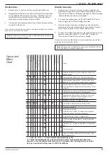
CLASS
CHANGE
- +
AUX
24V
FIRE PANEL
Non latching alarm
remotely set by
an external source
Figure 7 Connecting the Class change circuit


