

Mounting instructions
In order to minimise the installation time, it is strongly recommended, that
the following procedure is followed:
1
Remove plastic fascia by removing the two screws from the top
plastic cover.
2
Disconnect the two secondary transformer wires from the terminals
marked ‘AC~’ on the PCB. These are located on the right-hand side
of the fire panel.
3
Remove the two screws that hold the bottom plastic cover in place,
then lift away from fire panel housing. Store cover assembly in a safe
place to prevent damage during initial installation.
NOTE: DO NOT REMOVE THE PCB FROM THE PLASTIC
MOULDING.
4
Using the back box as a Drill template, mark through fixing positions,
prepare the fixing holes, and fit onto wall using an appropriate
mounting system.
Ensure the back box is not contaminated with drilling debris, e.g.
brick dust, as this can adversely affect the electronic circuitry.
5
Prepare cable entries via the 20mm knockouts provided in the top
and rear of back box using appropriate glanding system.
6
Remove any debris from the back box.
Wiring mains and battery
1
Configure the Auxiliary relay link for fire or fault operation. The
factory default setting is activation on fault.
2
Connect mains wiring to terminal block in the back box as marked.
NOTE: AN EARTH CONNECTION MUST BE MADE TO THE
TERMINAL BLOCK AS MARKED.
3
With the mains supply isolated, replace the lower plastic cover
assembly containing the PCB. Ensure the battery wires are routed to
the top left-hand side of the back box and the transformer secondary
wires are routed towards the right hand side. The PCB locating holes
should engage on the metal mounting tabs.
4
Reconnect the transformer secondary wires to the PCB terminals
marked ‘AC’.
Note: Polarisation of this connection is unimportant
5
Fit and tighten the two securing screws that hold the PCB moulding
in place. Ensure that the moulding has properly engaged at the
bottom of the metal back box. Do not over tighten two retaining
screws.
6
Fit battery into left-hand side of the back box and connect battery
using leads supplied. Ensure correct polarity is always observed.
The panel is now active and will indicate a ‘POWER FAULT’ and
“GENERAL FAULT” until the mains supply is re-instated, and
the panel ‘RESET’.
7
Instate the mains supply, enter access code then press the ‘RESET’
button, see operating instructions.
8
Check panel is operating normally. The panel should only show the
green “POWER ON” indicator.
9
You have now proved that the panel is free of faults.
2
61640610 issue 6_8/02
1 & 2 zone - Fire alarm panels
Battery
leads
System
fuses
Transformer
AC low volts
input
Locating points
for enclosure tabs
(In two positions)
8K2
E.O.L
resistors
125mA
1A
315mA
315mA
1.6A
Lower PCB cover
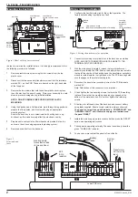
Figure 2
Terminals and
fuses
View on back of pcb
(Some components not shown for clarity)
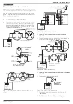
Battery
leads
Locating
points for
enclosure
tabs
(In two positions)
PCB
Sounder
FAULT/FIRE
AUXILIARY RELAY
(Shown in default “FAULT” position)
black
red
Figure 3 Setting the auxiliary relay operation
PCB TERMINAL
BLOCKS
BATTERY
CABLE ENTRY
POINTS TOP AND REAR
METAL
HOUSING
SECONDARY
TRANSFORMER
WIRES
TOP
COVER
FIXING
POINTS
BOTTOM
COVER
FIXING
POINTS
Figure 1 Panel with top cover removed


