61 | UPStealth® 2 User Manual
UPStealth 2 Battery Panel & Battery Module
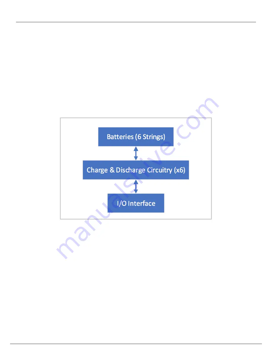
The Battery Panel and Battery Module are identical 500W battery packages with different form factors. These
devices will continuously monitor the six internal nickel-zinc battery strings to make sure they are properly charged
and discharged. The device will generally be in one of three states: Charging (Blue LED is ON), Discharging (Green
LED is ON), or Monitoring the Batteries (White LED is blinking). A fault (Red LED is ON) can occur and will be in a state
where it can neither charge or discharge. These devices communicate via CAN bus across the battery Digital and DC
Power Interconnect Cable with the UPStealth 2 UPS 1000W. Upon loss of power the UPStealth 2 UPS 1000W will signal
the Battery Panel/Battery Module to enable its battery DC bus to supply 57-43Vdc to the UPStealth 2 UPS 1000W
which will convert the battery DC bus to 120Vac Pure Sine wave to support up to a 1000W load. When not charging or
discharging the batteries will be in “monitor mode” with a self-discharge of approximately 3% per month (depending
on temperature and state of charge). When battery voltage drops below a set threshold due to self-discharge, the
batteries will perform a top off charge.
UPStealth 2 Battery Panel and Module Block Diagram
Содержание UPStealth 2
Страница 2: ......
Страница 71: ...UPStealth 2 User Manual 68 Notes ...
Страница 72: ...69 UPStealth 2 User Manual Notes ...
Страница 73: ......


