


INSTALLATION AND OPERATING INSTRUCTIONS:
Motor spindle, HF150-003 series
Zimmer GmbH
•
Im Salmenkopf 5
•
77866 Rheinau, Germany
•
+49 7844 9138 0
•
+49 7844 9138 80
•
www.zimmer-group.com
26
EN / 2020-10-22
DDOC00746 / -
10.3.1 Checking the clamping force
►
Check the clamping force of the clamping system before commissioning.
Ö
Use an appropriate clamping force measurement device that corresponds to the holder.
Ö
The clamping force must be >8 kN.
Ö
If the clamping force is below 8 kN, the clamping set must be cleaned.
Ö
If the clamping force continues to be below 8 kN after cleaning, the tool clamp must be replaced.
Ö
If the clamping force continues to be below 8 kN after being replaced, the tool clamp must be replaced by the
manufacturer.
Ö
Therefore, the complete motor spindle on the machine or system must be replaced.
10.4 Checking the tool interface (analog sensor and switching states)
DANGER:
Risk of fatal injury as a result of prohibited tool interface clamping states!
Ö
The motor spindle may be operated only if the state "Clamped with tool" is fulfilled.
Ö
Otherwise, a loss/ejection of the tool during operation/rotation cannot be ruled out!
Ö
Injury to personnel or material damage may result.
The analog sensor installed in the motor spindle monitors the clamping states of the tool interface. The analog sensor
outputs corresponding values as a voltage value [V] based on the clamping state.
The motor spindle converts the signal from the analog sensor into digital switching states.
Possible clamping states:
•
Clamped without tool (tool clamp completely retracted)
•
Clamped with tool (tool clamp actuated with tool)
•
Tool unclamped (tool clamp is completely extended)
Ö
Make sure that it is not possible to operate the motor spindle outside of the required switching states.
Ö
Use an appropriate switching logic to ensure that operation/rotation of the motor spindle is not possible.
Ö
See the “Technical datasheet” circuit diagram.
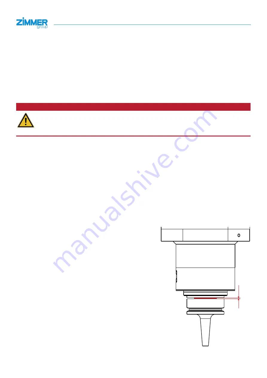
Check the function of the "Clamped with tool" switching state with the
following steps:
►
Insert a tool holder into the spindle shaft.
►
Push a feeler gauge with a thickness of 0.2 mm between the tool
holder and HTS plane face of the spindle shaft.
►
Actuate the tool clamp.
►
Check the switching state.
Ö
The "Clamped with tool" switching state must not be displayed.
►
Rotate the spindle shaft 360°.
Ö
The "Clamped with tool" switching state must not be displayed
during the process.
0,2